Single aperture multiple optical waveguide transceiver

a transceiver and optical waveguide technology, applied in the field of single aperture lidar and velocity measurement systems, can solve the problems of surface scattering impinging light, difficult at high pulse power, and real-world optical elements that do not behave ideally, so as to reduce back reflection, reduce coupling efficiency, and improve isolation

Active Publication Date: 2012-05-29
OPTICAL AIR DATA SYST
View PDF19 Cites 46 Cited by
  • Summary
  • Abstract
  • Description
  • Claims
  • Application Information

AI Technical Summary

Benefits of technology

[0031]Note that in this example, the image will appear at a distance v=150.8 mm from the lens, or about 0.8 mm from the tip of the transmitter waveguide, away from the lens. The tip of the receiver optical waveguide could be recessed slightly the tip of the transmitter, but if the focal length of the lens is long compared to this offset (as it is in our example) the tip of the receiver optical waveguide could be placed in the same plane as the tip of the transmitter fiber without significant coupling loss because the image will only be slighly larger (defocused).
[0032]One can see from equation (2) that as the target recedes from the transceiver, the image size diminshes (as R goes to infinity, D′ goes to zero). Thus, for a given distance between the receiver and transmitter waveguides, there is a limit to the range at which this transceiver works. This range limit depends on the size of the waveguides as well. For example, larger waveguides produce beams with larger divergence. It is also possible to increase the range by offsetting, or staggering, the output of one waveguide towards the lens with respect to the other but this requires careful design so that one waveguide will not clip the beam of the other.
[0040]Further improvements in isolation (at least 10 dB) can be realized by reducing the back reflection from the waveguide tips, either by applying an AR coating to the tips, or angle polishing them. Even more isolation can be realized by placing lower index or even opaque media between the two waveguides, although this might be difficult in some cases (like the multiple waveguide configuration of FIG. 11c).
[0041]In an embodiment where two waveguides are located at the focal point of the 150 mm focal length lens and the distance to the target is 30 m, the radius of the spot 38 is 125 μm, which means that spacing the input and output waveguides at 30 μm will ensure that the detector is within the spot 38. The most intense part of the image is at the tip of the transmitter waveguide, so the receiver waveguide is preferably placed to the side of the transmitter waveguide, which reduces the coupling efficiency compared to using a single waveguide for transmit and receive. In our example, the power coupled into the receiver waveguide will be exp(−2(30 / 125)2)=89% of what it is coupled into the transmitter waveguide because of the Gaussian intensity distribution of the image. The 11% loss compared to the single waveguide approach of FIG. 4 is acceptable given the greatly improved isolation, over 30 dB better than commercially available
[0042]Note that this loss relative to a single waveguide transceiver was calculated at a range of 30 meters. If the target were closer, the image size would increase according to the simple lens equation, and the loss relative to a single waveguide transceiver is smaller. The actual signal strength remains constant because as the image size increases, the amount of light coupled into the fixed receiver fiber decreases, but this is compensated by the increase in power collected from the closer target.
[0046]Another important consideration in the design of a transceiver in accordance with the invention is the reflection from the optical elements in the aperture shared by the waveguides. For two waveguides coupled to a plano-convex lens, the plane surface of the lens creates a mirror image of the waveguide directed back at itself with intensity equal to the reflection coefficient of the plane surface (about 4% for air-to-glass transitions). This image will be at twice the distance between the waveguide and the lens. For single mode waveguides perfectly aligned with each other, the coupling coefficient at distances much larger than the core size is extremely small. Moreover, any backreflection can be reduced by placing an anti-reflection (AR) coating on the surface of the lens.

Problems solved by technology

This geometry is problematic because it creates a ‘blind spot’14 in front of the receiver in the region where the transmitter beam and receiver FOV do not overlap.
This is worse when the LIDAR is used on partially polarizing targets or even more so in the case of purely specular targets.
Unfortunately, real-world optical elements do not behave ideally, and some of the illuminating light from the laser 2 necessarily makes its way to the receiver.
Additionally, imperfections on the reflecting surfaces scatter the impinging light in all directions.
The ‘leaked’ light from the transmitter direction does not pose a problem as long as adequate steps are taken to shield the detector from it, but this can be difficult at high pulse powers.
Since fiber optic components like circulators are composed of many small optical elements similar to PBS's they suffer from the same problems.
While this may be acceptable for telecommunication systems, it presents a problem in LIDAR systems, as return beams are usually reduced by more than 60 dB relative to the transmitter.
In range finding applications, the isolation may be so inadequate and the pulse peak power so high that the light from the transceiver alone temporarily blinds sensitive detectors.
In this situation one can temporarily power off the receiver (gating), but this creates a blind spot at close range due to the switching times involved (or detector recovery time if it is not switched off).
For Doppler CW LIDAR systems, insufficient isolation causes a permanent Doppler signal at zero velocity (also called the “v=0 problem”).
This signal will generally have a linewidth equal to that of the transmitter laser, and thus limit the minimum speed that can be detected.
Pulsing is required to eliminate the zero-velocity Doppler signal to allow measurement of very low speeds, but this is ineffective if one desires to do velocity sensing and very close ranges.
However this approach also suffers from an isolation comparable to the circulator approach.
Another drawback to this method is that light in the inner cladding is multimode, making coherent detection for velocity sensing poor so the approach described by U.S. Pat. No. 6,757,467 is mostly relegated to range finding.
However it is also clear that the maximum sensing range of this approach is limited by the space between the receiver and transmitter fibers.

Method used


Image

  • Single aperture multiple optical waveguide transceiver
  • Single aperture multiple optical waveguide transceiver
  • Single aperture multiple optical waveguide transceiver

Examples


Embodiment Construction

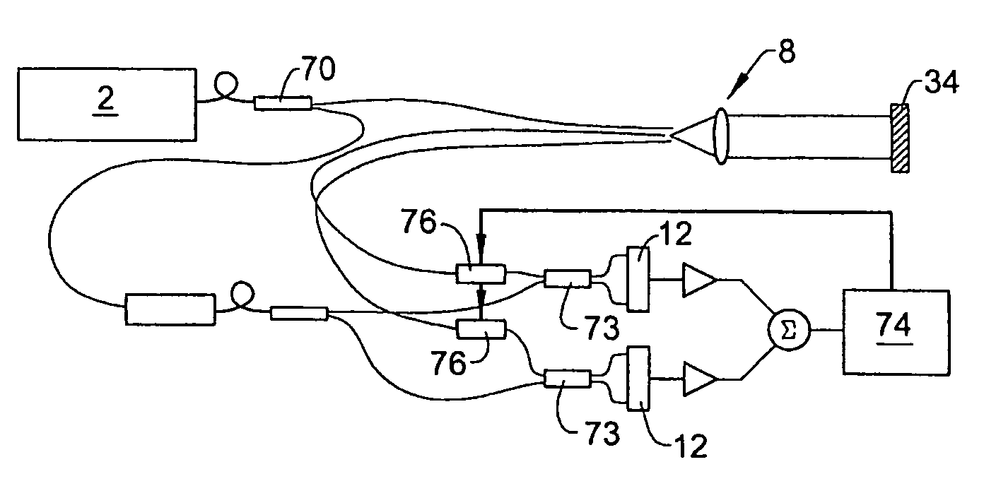
[0064]In accordance with the invention a unique single-aperture, multi-axial transceiver is provided that is particularly useful in a LIDAR system for detecting low velocities at increased ranges. FIG. 7 illustrates a simple biaxial version of the invention. In the embodiment of FIG. 7 the laser transmitter source 2 and the detector 12 share a single objective 8. The objective may comprise multiple optical elements, which may be refractive, reflective, diffractive, or a combination of all, as long as the combination provides the necessary imaging properties. A single optical element is preferred because fewer optical surfaces provide better isolation for the reasons described above with regard to FIG. 5.

[0065]The output aperture of the laser is preferably made small compared to the aperture of the objective 8, and it is placed at or near the focal plane of the objective to produce a substantially collimated output beam 4. In the embodiment of FIG. 7, the output of the laser 2 is dis...


PUM

PropertyMeasurementUnit
distanceaaaaaaaaaa
diameteraaaaaaaaaa
diameteraaaaaaaaaa

Abstract

A single-aperture, multi-axial transceiver is provided that is particularly useful in a LIDAR system for detecting low velocities at increased ranges. The system is particularly useful in systems that are required to measure very low velocities and very short distances as well as to provide an operating range of hundreds of meters. The transceiver uses closely spaced waveguides placed near the focal point of a single objective 8 to form input and detector apertures. Preferably the input and detector apertures are spaced from each other by less than about 80 μm. In an embodiment using light with a wavelength of 1550 nm, the spacing is preferably about 30 μm.

Description

[0001]This application is the national stage of International Application Number PCT / US2006 / 043928, filed Nov. 13, 2006, which was published in English, and claims priority of U.S. Provisional Application No. 60 / 735,164, filed Nov. 10, 2005.TECHNICAL FIELD[0002]This invention relates to the art of optical transceivers. The invention finds particular applicability in single aperture LIDAR and velocity measurement systems using fiber optic elements.BACKGROUND ART[0003]This invention relates generally to optics, optical waveguides, and optical systems and devices. It is especially relevant to LIDAR (Light Detection And Ranging) and optical communication systems where optimal performance at a short range is desired. In its simplest form, a LIDAR system has an optical transmitter (typically a laser) and an optical receiver placed side-by-side, pointed in the same direction. Collectively these are known as a transceiver. The transmitter provides a short-pulsed beam of light that is direct...

Claims


Application Information

Patent Timeline
Patent Type & Authority Patents(United States)
IPC IPC(8): H04B10/00
CPCG01S7/4812G01S7/4818G02B6/4246G02B6/3636Y10T29/49194Y10T29/49002G02B6/3652
Inventor LECLAIR, LANCE RICHARDMAMIDIPUDI, PRIYAVADAN
Owner OPTICAL AIR DATA SYST
Why Eureka
Try Eureka