Control device of internal combustion engine

a control device and internal combustion engine technology, applied in the direction of electrical control, process and machine control, instruments, etc., can solve the problems of deteriorating drivability, inability to apply at the acceleration time, and difficulty in avoiding engine fluctuation, so as to achieve the effect of not deteriorating drivability

Active Publication Date: 2012-05-29
MITSUBISHI MOTORS CORP
View PDF9 Cites 0 Cited by
  • Summary
  • Abstract
  • Description
  • Claims
  • Application Information

AI Technical Summary

Benefits of technology

[0027]It is therefore an object of the invention to provide a control device of an internal combustion engine which is advantageous in securing an implementation frequency of an activation processing or a reproduction processing of an exhaust purification unit without deteriorating the drivability.

Problems solved by technology

For this reason, for example, when the air-fuel ratio is temporarily modulated to be rich at the time of acceleration, it is difficult to avoid the generation of the fluctuation in the engine.
However, the above-mentioned technique can be applied to cases where the vehicle is normally driven or the engine is in the idle state, but it cannot be applied at the time of acceleration.
That is, when the feed-back control of the driving control parameter such as at the time of acceleration of the vehicle does not function and only the feed-forward control is performed, performing the compulsory modulation of the air-fuel ratio at the time of acceleration generates the fluctuation in engine and becomes a cause of deteriorated drivability.
However, when a situation where the compulsory modulation of the air-fuel ratio can be performed is restricted, it is disadvantageous in securing a processing that should be performed with respect to the exhaust purification unit, i.e., an implementation frequency of the activation processing of the exhaust purification unit.
However, since the normal alternator cannot impart a positive torque to the internal combustion engine, it can be substantially applied to the case of (the target revolution)<(the actual revolution).

Method used


Image

  • Control device of internal combustion engine
  • Control device of internal combustion engine
  • Control device of internal combustion engine

Examples


first embodiment

[0063]Next, a control device of an internal combustion engine of an embodiment of the present invention will be described with reference to FIGS. 1 to 5.

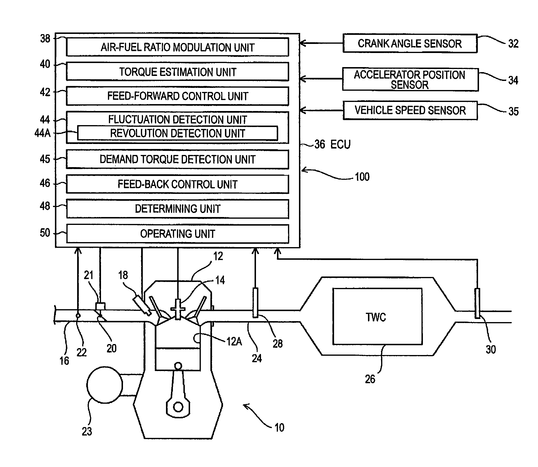
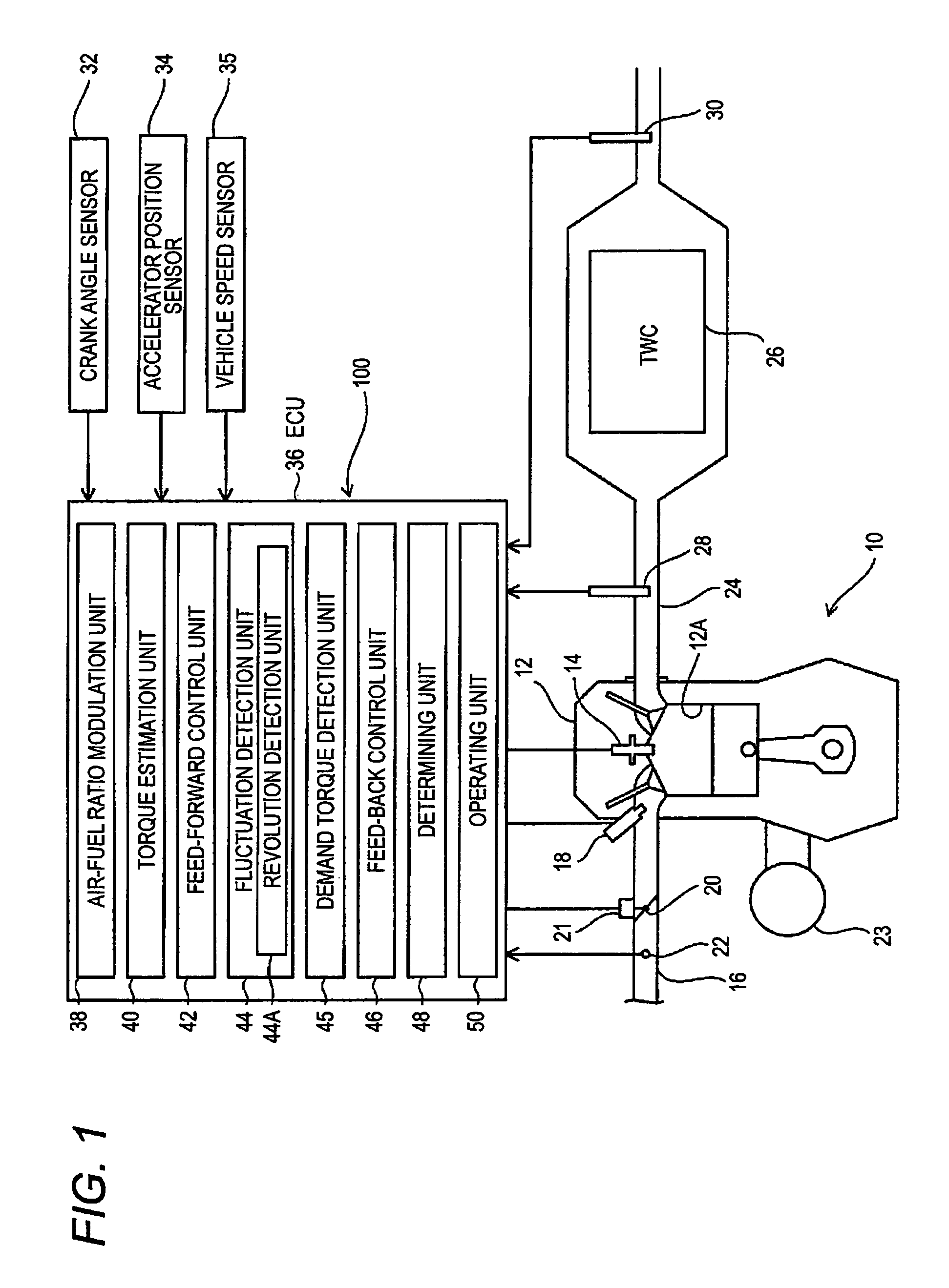
[0064]First of all, an engine (an internal combustion engine) 10 to which a control device 100 of the present invention is applied will be described.

[0065]As shown in FIG. 1, in the present embodiment, the engine 10 mounted on a vehicle is a gasoline engine.

[0066]The engine 10 is an intake flow path injection type and includes a cylinder head 12, an ignition plug 14, an intake flow path 16, a fuel injection valve 18, a throttle valve 20, an air flow sensor 22, a motor (an alternator or a generator) 23 or the like.

[0067]In addition, the engine 10 includes an exhaust flow path 24, a three-way catalyst 26, an upstream side oxygen sensor 28, a downstream side oxygen sensor 30, a crank angle sensor 32, an accelerator position sensor 34, a vehicle speed sensor 35, an ECU 36, and the control device 100 according to the present invention.

[0...

second embodiment

[0215]Next, a second embodiment of the present invention will be described with reference to FIGS. 6 to 8. Furthermore, a configuration of the control device 100 is described by the use of FIG. 1.

[0216]Furthermore, in the following embodiment, the parts, which are identical to or correspond to the first embodiment, will be noted by the same reference numerals and the description thereof will be omitted.

[0217]In the second embodiment, since the operating unit 50 is different from that of the first embodiment and other configurations are the same as those of the first embodiment, hereinafter, the description will focus on the operating unit 50.

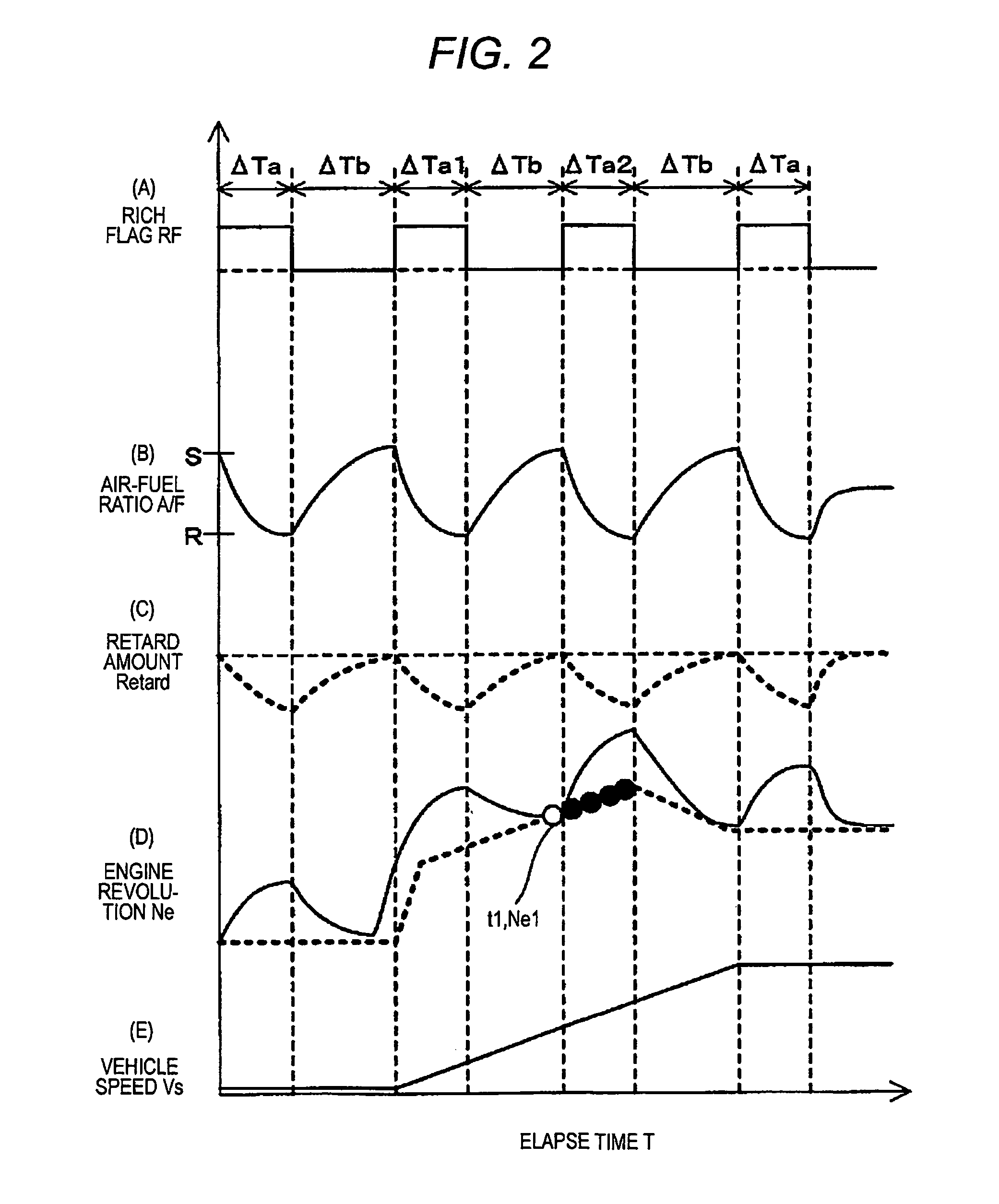
[0218]The operating unit 50 detects the revolution of the engine 10 as the fluctuation suppression target value based on least squares method using the detection result of the revolution detection unit 44A and operates the feed-back control unit 46 so as to make the actual revolution close to the target revolution.

[0219]The wave forms of the res...

third embodiment

[0247]Next, a third embodiment will be described with reference to FIGS. 9 and 10.

[0248]The third embodiment is a modified example of the first embodiment and is different from the first embodiment in that an engine 60 is a diesel engine.

[0249]For this reason, the third embodiment is different from the first embodiment in that the driving control parameter is the fuel injection amount, the specific configuration of the exhaust purification unit thereof is different from that of the first embodiment, and other configurations are almost the same as the first embodiment, so description below will focus mainly on the points different from the first embodiment.

[0250]As shown in FIG. 9, the engine 60 includes the cylinder head 12, the intake flow path 16, the throttle valve 20, and the air flow sensor 22.

[0251]On the cylinder head 12, a fuel injection valve 64 for injecting the fuel into the combustion chamber (the cylinder chamber) 12A is provided.

[0252]In the third embodiment, as the ex...


PUM


Abstract

A control device of an internal combustion engine includes: an air-fuel ratio modulator, performing modulation of an air-fuel ratio of an exhaust which flows in an exhaust purifier provided in an exhaust system of the internal combustion engine; a fluctuation detector, detecting a fluctuation of the internal combustion engine due to the modulation of the air-fuel ratio performed by the air-fuel ratio modulator; a feed-back controller, performing feed-back control of a driving control parameter of the internal combustion engine so as to suppress the fluctuation detected by the fluctuation detector; a determiner, determining whether or not a driving state of the internal combustion engine is in an operating area of the feed-back controller; and an operator, setting a fluctuation suppression target value, which is a target value for suppressing the fluctuation of the internal combustion engine, to operate the feed-back controller based on the fluctuation suppression target value, when the determiner determines that the driving state of the internal combustion engine is not in the operating area of the feed-back controller, while the air-fuel modulator performs the modulation of the air-fuel ratio.

Description

BACKGROUND OF THE INVENTION[0001]The present invention relates to a control device of an internal combustion engine.[0002]In an exhaust system of an internal combustion engine which is mounted on a vehicle, an exhaust purification unit for removing CO (carbon monoxide), HC (hydrocarbon), NOx (nitrogen oxide), and particulate matter (PM), which are contained in the exhaust of the internal combustion engine, is provided.[0003]In a case where the internal combustion engine is a gasoline engine, a three-way catalyst is widely used as the exhaust purification unit.[0004]The three-way catalyst is a catalyst that oxidizes CO to CO2, oxidizes HC to CO2 and H2O and reduces NOx to O2 (oxygen) and N2 (nitrogen).[0005]Furthermore, in a case where the internal combustion engine is a diesel engine, as the exhaust purification unit, the following are used in combination. That is, there are an oxidation catalyst, a NOx storage catalyst, and a diesel particulate filter (DPF).[0006]The oxidation cata...

Claims


Application Information

Patent Timeline
Patent Type & Authority Patents(United States)
IPC IPC(8): F02D41/14F01N3/00F02D28/00
CPCF02D41/1454F02D41/365F02P5/1514F01N2900/0411Y02T10/22F02D2200/501Y02T10/46F02D2200/10Y02T10/12Y02T10/40
Inventor TAKAHASHI, MASASHI
Owner MITSUBISHI MOTORS CORP
Why Eureka
Try Eureka