Control Apparatus for Power Transmission System

a technology of power transmission system and control apparatus, which is applied in the direction of engine-driven generators, transportation and packaging, etc., can solve the problems of engine stopping by cutting off fuel, drivability in traveling under normal conditions not in the event, and so as to reduce the rotation speed of the output rotating member of the electrical transmission mechanism, prevent overspeed of the first electric motor, and improve the effect of drivability

Active Publication Date: 2017-06-15
TOYOTA JIDOSHA KK
View PDF1 Cites 9 Cited by
  • Summary
  • Abstract
  • Description
  • Claims
  • Application Information

AI Technical Summary

Benefits of technology

[0007]The disclosure provides a control apparatus that is used for a power transmission system including an electrical transmission mechanism and a mechanical transmission mechanism in series with each other and that is able to prevent an overspeed of a first electric motor in the event of malfunction of the electrical transmission mechanism without deteriorating drivability in traveling under normal conditions of the electrical transmission mechanism.
[0013]According to the first aspect of the disclosure, when it is determined that there is the malfunction in the electrical transmission mechanism and the operation of the engine is stopped, the mechanical transmission mechanism is caused to start upshifting by the time the rotation of the engine stops. Therefore, when the rotation of the engine is stopped as a result of a stop of the operation of the engine, the rotation speed of the output rotating member of the electrical transmission mechanism is decreased as compared to that before it is determined that there is the malfunction in the electrical transmission mechanism. Thus, the rotation speed of the first electric motor is lower in absolute value than that in the case where the mechanical transmission mechanism is not caused to upshift on the basis of the relative relationship among the rotation speeds of the rotating elements of the differential mechanism, so an overspeed of the first electric motor is prevented. This means that, in traveling under normal conditions of the electrical transmission mechanism, it is not required for the vehicle to travel while avoiding a traveling range, which is higher than or equal to the rotation speed of the input rotating member of the mechanical transmission mechanism and which leads to an overspeed of the first electric motor when the rotation of the engine is stopped. Thus, in the power transmission system including the electrical transmission mechanism and the mechanical transmission mechanism in series with each other, it is possible to prevent an overspeed of the first electric motor in the event of a malfunction of the electrical transmission mechanism without deteriorating drivability in traveling under normal conditions of the electrical transmission mechanism.
[0014]According to the second aspect of the disclosure, the mechanical transmission mechanism is caused to start upshifting when the estimated rotation speed of the first electric motor falls within the predetermined overspeed range in a state where the rotation of the engine is stopped, so it is possible to appropriately prevent an overspeed of the first electric motor in the event of a malfunction of the electrical transmission mechanism.
[0015]According to the third aspect of the disclosure, the mechanical transmission mechanism is caused to upshift such that the speed ratio becomes the estimated speed ratio of the mechanical transmission mechanism at which the rotation speed of the first electric motor falls outside the predetermined overspeed range in a state where the rotation of the engine is stopped, so it is possible to reliably prevent an overspeed of the first electric motor in the event of a malfunction of the electrical transmission mechanism.
[0016]According to the fourth aspect of the disclosure, the mechanical transmission mechanism is the automatic transmission in which the plurality of speed positions are selectively established through a shift resulting from engaging and releasing the engagement devices, and the shift control unit causes the mechanical transmission mechanism to proceed with upshifting by engaging the engagement devices for establishing the speed position after upshifting. Therefore, it is possible to quickly decrease the rotation speed of the output rotating member of the electrical transmission mechanism, with the result that it is possible to reliably prevent an overspeed of the first electric motor in the event of a malfunction of the electrical transmission mechanism. That is, in the case of shift control for causing the mechanical transmission mechanism to proceed with upshifting by engaging the engagement devices for establishing the speed position after upshifting, the rotation speed of the input rotating member of the mechanical transmission mechanism decreases with the process of engagement for upshifting. Therefore, as compared to the case of shift control for, after the rotation speed of the input rotating member of the mechanical transmission mechanism has decreased naturally, engaging the engagement devices for establishing the speed position after upshifting, the rate of decrease in the rotation speed of the input rotating member of the mechanical transmission mechanism increases, so it is possible to reliably prevent an overspeed of the first electric motor in the event of a malfunction of the electrical transmission mechanism.
[0017]According to the fifth aspect of the disclosure, the rotation speed of the first electric motor is decreased in absolute value, as compared to the case where the mechanical transmission mechanism is not caused to upshift, on the basis of the relative relationship among the rotation speeds of the three rotating elements of the differential mechanism, so an overspeed of the first electric motor is prevented.

Problems solved by technology

Incidentally, when there is a malfunction that prevents the first electric motor from controlling the electrical transmission mechanism, the engine may be stopped by cutting off fuel.
At this time, a high rotation speed of the input rotating member of the mechanical transmission mechanism may lead to an overspeed of the first electric motor.
However, the above restriction restricts acceleration of the vehicle up to a high vehicle speed at a low gear ratio even when a driver's acceleration request is large, so there is a possibility that drivability in traveling under normal conditions not in the event of malfunction is deteriorated.

Method used


Image

  • Control Apparatus for Power Transmission System
  • Control Apparatus for Power Transmission System
  • Control Apparatus for Power Transmission System

Examples


embodiment

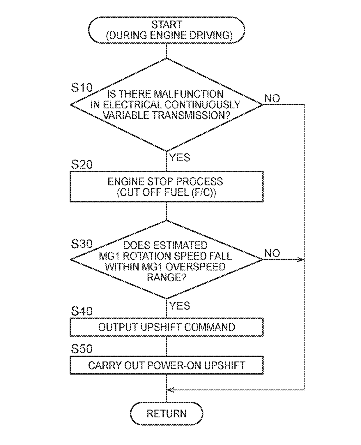
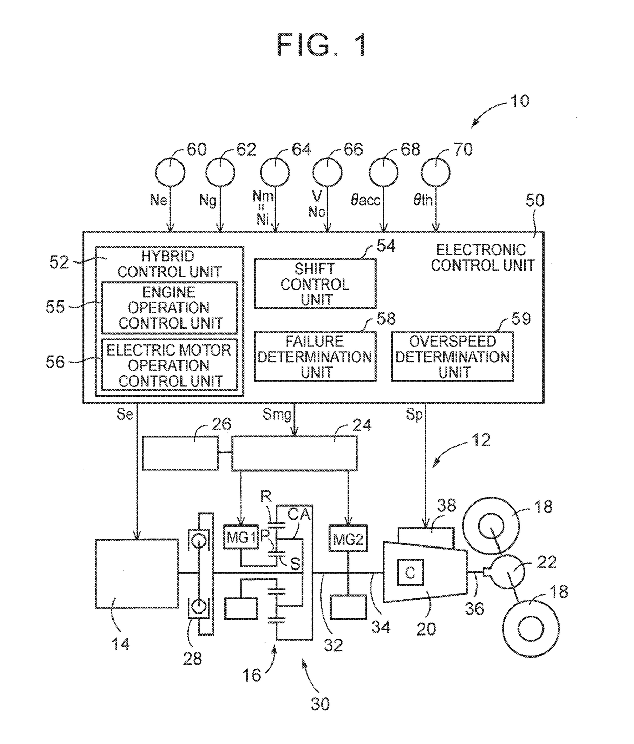
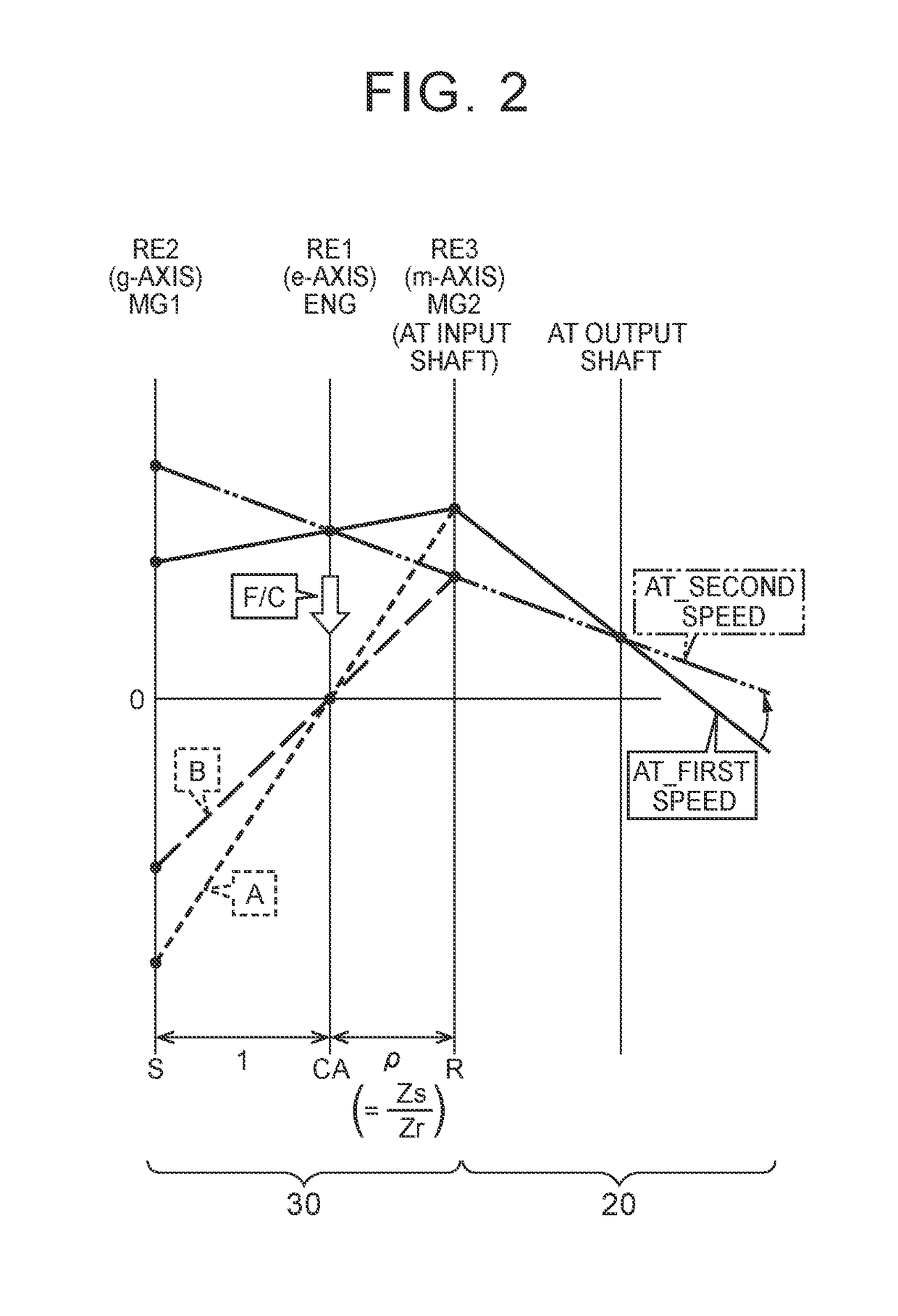
[0025]FIG. 1 is a view that illustrates the schematic configuration of a power transmission system 12 provided in a vehicle 10 to which the disclosure is applied, and is a view that illustrates a relevant portion of a control system for various control in the vehicle 10. In FIG. 1, the vehicle 10 is a hybrid vehicle including an engine 14, a first electric motor MG1 and a second electric motor MG2. The power transmission system 12 includes a power distribution mechanism 16 and an automatic transmission (AT) 20. The power distribution mechanism 16 serves as a differential mechanism in which each of the engine 14, the first electric motor MG1 and the second electric motor MG2 is coupled to any one of a plurality of rotating elements (rotating members) such that power is transmitted. The automatic transmission (AT) 20 is arranged between the power distribution mechanism 16 and drive wheels 18. In the power transmission system 12, power (when not specifically distinguished from one anot...


PUM


Abstract

When an electrical continuously variable transmission malfunctions and the operation of an engine is stopped, an automatic transmission is caused to upshift. Therefore, when the rotation of the engine is stopped as a result of a stop of the operation, an AT input rotation speed is decreased as compared to that before it is determined that there is a malfunction in the electrical continuously variable transmission. Thus, an MG1 rotation speed is decreased in absolute value as compared to when the automatic transmission is not caused to upshift, so an overspeed of a first electric motor is prevented.

Description

INCORPORATION BY REFERENCE[0001]The disclosure of Japanese Patent Application No. 2015-240644 filed on Dec. 9, 2015 including the specification, drawings and abstract is incorporated herein by reference in its entirety.BACKGROUND[0002]1. Technical Field[0003]The disclosure relates to a control apparatus for a power transmission system including an electrical transmission mechanism and a mechanical transmission mechanism in series with each other.[0004]2. Description of Related Art[0005]There is well known a control apparatus for a power transmission system including an electrical transmission mechanism, a second electric motor and a mechanical transmission mechanism. The electrical transmission mechanism includes a differential mechanism and a first electric motor. An engine is coupled to the differential mechanism such that power is transmitted. The first electric motor is coupled to the differential mechanism such that power is transmitted. A differential state of the differential...

Claims


Application Information

Patent Timeline
Patent Type & Authority Applications(United States)
IPC IPC(8): B60W20/50F16H61/12F16H61/02B60L50/16
CPCB60W20/50F16H2061/1296F16H61/12F16H61/0204B60K6/365B60K6/387B60K6/40B60K6/547B60W10/02B60W10/06B60W10/08B60W10/111B60W10/115B60W10/16B60W2510/0638B60W2510/081B60W2710/021B60W2710/0666B60W2710/08B60W2710/1005B60W2710/12B60K6/445B60W10/11B60W30/184B60W50/0097F16H3/66F16H3/727F16H2003/445F16H2200/2007F16H2200/2041F16H2200/2066F16H2200/2082Y02T10/62B60K6/24B60K6/26B60K6/36B60K6/46B60W10/10B60W10/12B60W20/00B60W50/02
Inventor KOBAYASHI, NOBUFUSAYOSHIKAWA, MASATOTANAKA, TAKAAKI
Owner TOYOTA JIDOSHA KK
Why Eureka
Try Eureka