Air-bypass valve control device

a control device and airbypass valve technology, applied in electric control, combustion air/fuel air treatment, machines/engines, etc., can solve the problems of deteriorating drivability, causing unfavorable air quality control, and generating unique noise, so as to prevent compressor surge without deteriorating drivability

Active Publication Date: 2019-09-03
SUBARU CORP
View PDF25 Cites 0 Cited by
  • Summary
  • Abstract
  • Description
  • Claims
  • Application Information

AI Technical Summary

Benefits of technology

[0016]It is desirable to provide an air-bypass valve control device that prevents occurrence of compressor surge without deteriorating drivability.

Problems solved by technology

As a result, unique noise is possibly generated, and reliability of the turbocharger is possibly deteriorated due to application of a force to the blades of the compressor, the force being in a reverse direction from rotation of the blades.
However, regardless of adoption of the electric air-bypass valve, when the air-bypass valve is opened in a region where opening thereof is unnecessary under normal circumstances as a result of inappropriate control, a time response delay occurs to an increase in the supercharging pressure during re-acceleration, which deteriorates drivability (timely response to a driver's operation).
As a result, actuation noise that is generated during opening / closing of the air-bypass valve is no longer masked by the engine noise.
As a result, while the occurrence of the compressor surge can be prevented by actuation of the air-bypass valve, it is concerned that the actuation noise gives a sense of discomfort to a user.

Method used


Image

  • Air-bypass valve control device
  • Air-bypass valve control device
  • Air-bypass valve control device

Examples


example

[0032]A description will hereinafter be made on an example of an air-bypass valve control device, to which the present invention is applied.

[0033]The air-bypass valve control device of the example is provided in a turbocharged engine that is, for instance, mounted as a traveling power source on an automobile such as a passenger car and that has an electric air-bypass valve.

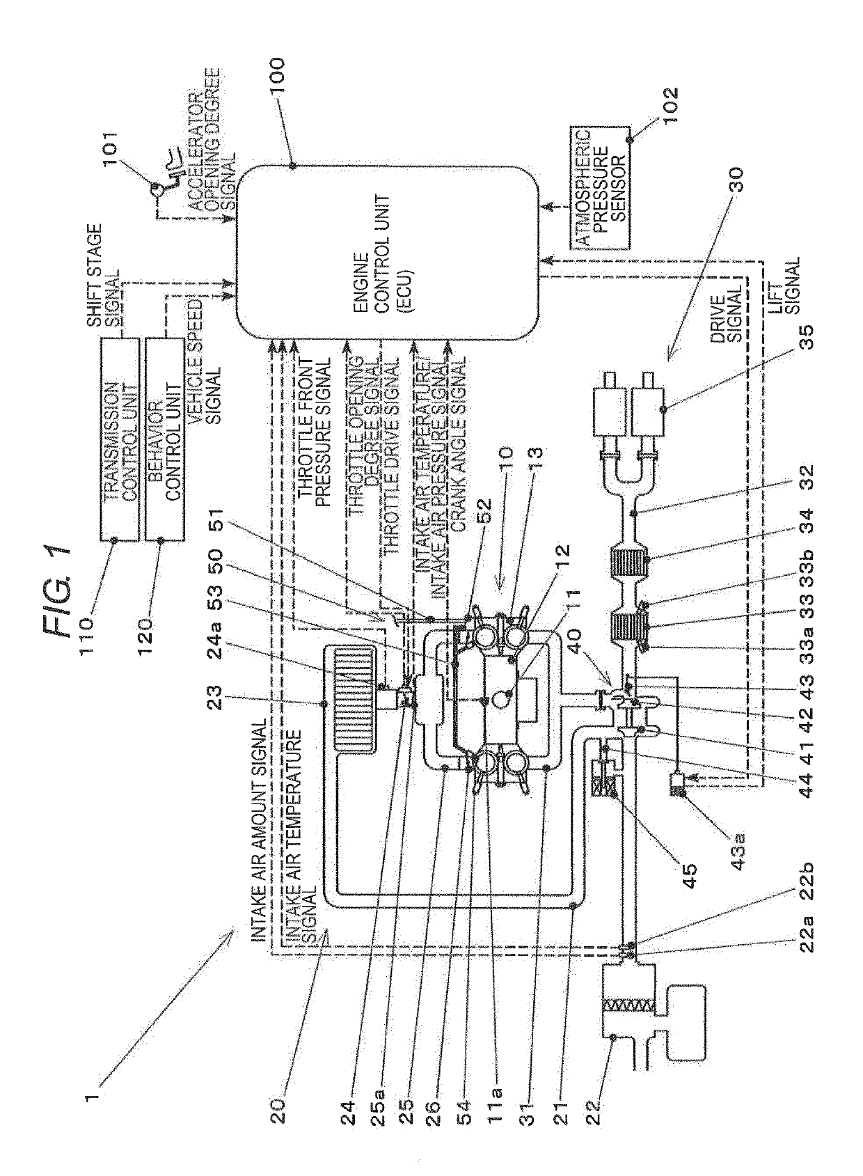
[0034]FIG. 1 is a view that schematically illustrates a configuration of an engine having the air-bypass valve control device of the example.

[0035]An engine 1 is a horizontally-opposed four-cylinder four-stroke DOHC direct injection gasoline engine, for instance.

[0036]The engine 1 includes a main body 10, an intake system 20, an exhaust system 30, a turbocharger 40, a fuel supply device 50, an engine control unit 100, and the like.

[0037]The main body 10 is a primary component of the engine 1 and has a crankshaft 11, a cylinder block 12, a cylinder head 13, and the like.

[0038]The crankshaft 11 is an output shaft of...

modified examples

[0207]The present invention is not limited to the example that has been described so far, and various modifications and changes can be made thereto. These modifications and changes also fall within the technical scope of the present invention. (1) The configurations of the engine and the air-bypass valve control device are not limited to those in the above example and can appropriately be changed.

[0208]For instance, a cylinder layout, the number of the cylinders, the valve drive method, the fuel injection method, and the like of the engine are not limited to the configuration in the example and can appropriately be changed.

[0209]In addition, the engine in the example is the turbocharged direct injection gasoline engine, for instance. However, the engine is not limited thereto. As long as an engine turbocharges and uses the throttle valve for output adjustment, the present invention can be applied thereto. (2) In the example, the necessity of the control, in which the air-bypass valv...


PUM


Abstract

An air-bypass valve control device is disposed in an engine. The engine includes an intake passage, a compressor, a throttle valve, an air-bypass passage and the air-bypass valve. The air-bypass valve control device includes an intake air amount detector, a controller. The intake air amount detector detects an intake air amount of the engine. The controller configured to temporarily bring the air-bypass valve into an opened state in the case where the intake air amount of the engine immediately before a decrease in an opening degree of the throttle valve is equal to or larger than a predetermined value when the opening degree of the throttle valve decreases at a predetermined speed or higher.

Description

CROSS-REFERENCE TO RELATED APPLICATIONS[0001]The present application claims priority from Japanese Patent Application No. 2016-148505 filed on Jul. 28, 2016, the entire contents of which are hereby incorporated by reference.BACKGROUND1. Technical Field[0002]The present invention relates to an air-bypass valve control device, the air-bypass valve opening / closing an air-bypass passage for a compressor of a turbocharger and, in particular to, an air-bypass valve control device that prevents occurrence of compressor surge without deteriorating drivability.2. Related Art[0003]A turbocharger provided in an automotive engine or the like, for instance, is a supercharger that uses a turbine driven by energy of exhaust gas to drive a compressor that compresses fresh air (combustion air).[0004]In the engine that turbocharges, when a throttle valve is rapidly closed from a state where a throttle valve opening degree is large and supercharging pressure is high, pressure is rapidly increased in a...

Claims


Application Information

Patent Timeline
Patent Type & Authority Patents(United States)
IPC IPC(8): F02M35/10F02D41/10F02D41/00F02D9/02F02D41/18F02B37/16F02B37/12
CPCF02D41/0005F02D41/0007F02M35/10386F02D9/02F02M35/10163F02B37/16F02D41/18F02D41/107Y02T10/42F02D2200/0408F02D2200/0411F02B2037/125Y02T10/144F02D2200/101F02B37/162F04D27/0215F04D27/0223Y02T10/12Y02T10/40
Inventor MURAMATSU, KONOSUKE
Owner SUBARU CORP
Why Eureka
Try Eureka