Print tape and a print cassette

a technology of print cassette and tape, which is applied in the field of print cassette, can solve the problems of conventional “laminated tape” being likely to gradually come unstuck from the curved surface of the adherend, and the tendency of the adherend to gradually come unstuck from the curved surfa

Inactive Publication Date: 2012-06-05
BROTHER KOGYO KK
View PDF27 Cites 3 Cited by
  • Summary
  • Abstract
  • Description
  • Claims
  • Application Information

AI Technical Summary

Benefits of technology

[0048]In other words, in the print tape according to the disclosure, the second base material adheres to the printing surface of the to-be-printed medium with the second adhesive layer. Then, the second base material is removed from the to-be-printed medium and, with the exposed second adhesive layer stuck to an adherend, the first base material which adhered to the to-be-printed medium with the first adhesive layer is removed. As a result, the first adhesive layer is separated together with the first base material from the to-be-printed medium and then, the printing surface of the to-be-printed medium is stuck to the adherend with the second adhesive layer. Consequently, the “laminated tape” can be stuck to the adherend.
[0049]In the print tape, the third base material adheres to the printing surface of the to-be-printed medium with the third adhesive layer. Then, the fourth base material is removed from the third base material and, with the exposed fourth adhesive layer stuck to an adherend, the first base material which adhered to the to-be-printed medium with the first adhesive layer is removed from the to-be-printed medium. As a result, the first adhesive layer is separated together with the first base material from the to-be-printed medium and then, the printing surface side of the to-be-printed medium is in a state of adhering to the third base material with the third adhesive agent, the third base material is stuck to the adherend with the fourth adhesive layer. Consequently, the “laminated tape” can be stuck to the adherend.
[0050]In the print tape of the present disclosure, the to-be-printed medium adhered to the first base material with the first adhesive layer and can thus keep the rigidity at least by the thickness of the first base material.
[0051]When the to-be-printed medium is stuck to the adherend, the first base material adhered to the to-be-printed medium, so that the to-be-printed medium can thus keep the rigidity at least by the thickness of the first base material. Thus, however thin the to-be-printed medium constituting the “laminated tape” is, the work of sticking the “laminated tape” to the adherend securely can be carried out.
[0052]In the print tape, when the to-be-printed medium is stuck to the adherend, the first base material adhered to the to-be-printed medium with the first adhesive layer. Thus, the to-be-printed medium can thus keep the rigidity at least by the thickness of the first base material and however thin the to-be-printed medium is, the work of sticking the to-be-printed medium to the adherend securely can be carried out. The first adhesive agent for forming the first adhesive layer is dispersed uniformly in a predetermined pattern. Therefore, even if the to-be-printed medium is stuck to the adherend, the clue for releasing the first base material from the to-be-printed medium is easy to make and after that, the first base material is easy to remove from the to-be-printed medium.
[0053]Examples of the predetermined pattern include a striped pattern, a grid pattern, and a polka-dot pattern.

Problems solved by technology

For this reason, when the conventional “laminated tape” is stuck to a curved face of an adherend, the conventional “laminated tape” would be likely to gradually come unstuck from the curved surface of the adherend due to insufficient elasticity or the like resulting from the thickness of the print tape.
Further, when the conventional “non-laminated tape” is stuck to a curved surface of an adherend, it would be likely to gradually come unstuck from the curved surface of the adherend due to insufficient elasticity or the like resulting from the thickness of a to-be-printed medium.

Method used


Image

  • Print tape and a print cassette
  • Print tape and a print cassette
  • Print tape and a print cassette

Examples


first embodiment

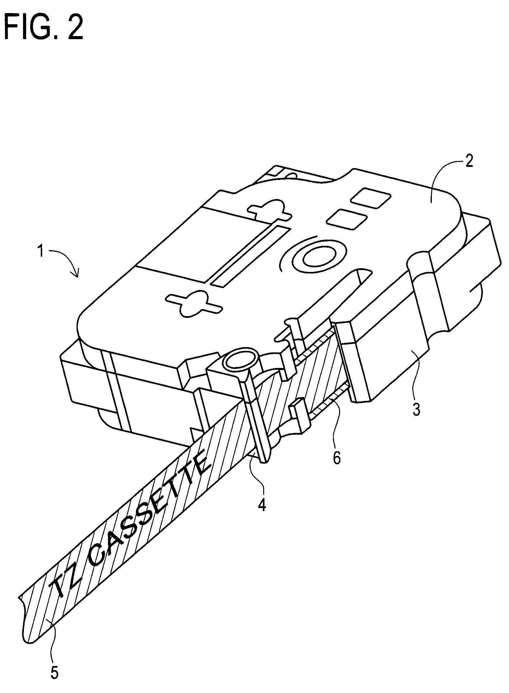
[0351]Incidentally, when the print cassette 1 of the first embodiment is set in a cassette mount of a tape printer, a thermal head H1 of the tape printer exists on the thermal head arrangement portion 20. Then, the first tape 11 and the ink ribbon 6 are nipped by the thermal head H1 and a platen roller P1 of the tape printer opposing the head H1.

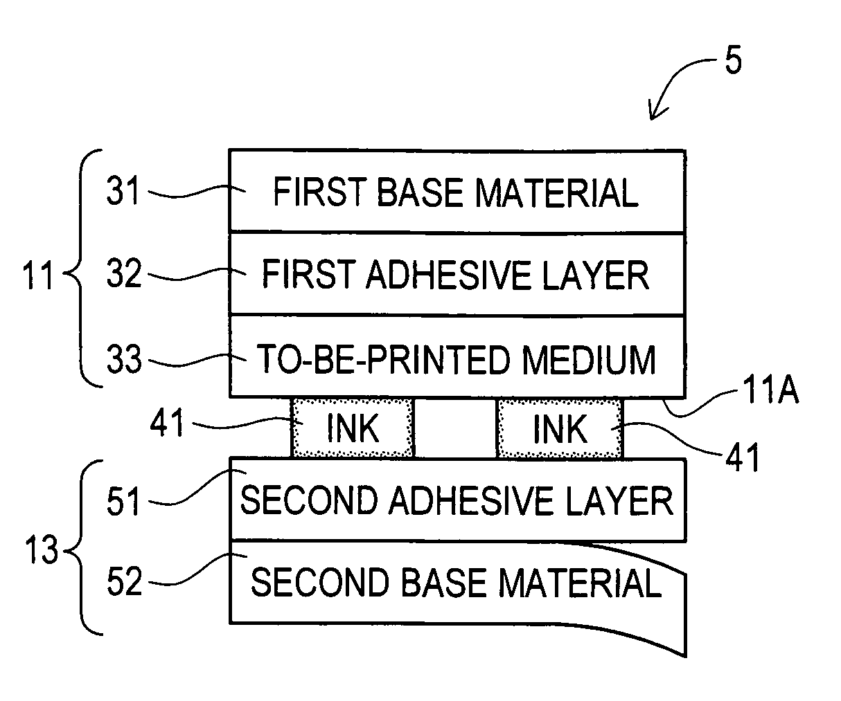
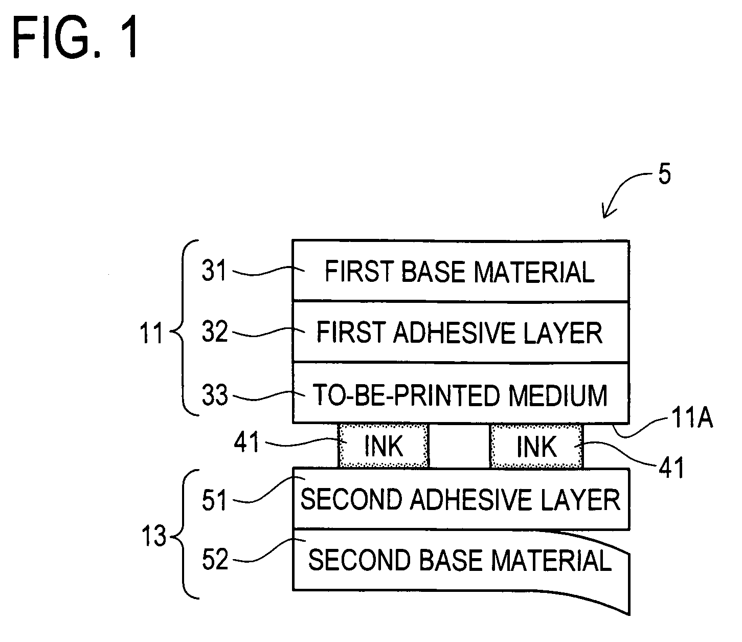
[0352]On the other hand, the second tape 13 has a second adhesive layer which is formed by being coated a second base material (a release sheet) having a sheet thickness of approximately 53 μm with a second adhesive agent of approximately 16 μm thick. Then, the second tape 13 is wound on the tape spool 12 with the second base material side outside. The second tape 13 wound in this way is guided by the feed roller 22 while the adhesive-coated surface of the second adhesive layer and the printing surface of the first tape 11 are overlapped with each other. As a result, the second tape 13 adheres to the first tape 11, and discharged outside the...

second embodiment

[0421]Incidentally, when the print cassette 101 of the second embodiment is set in a cassette mount of a tape printer, a thermal head H2 of the tape printer exists on the thermal head arrangement portion 120. Then, the first tape 111 and the ink ribbon 106 are nipped by the thermal head H2 and a platen roller P2 of the tape printer opposing the head H2.

[0422]On the other hand, the third tape 113 has a third adhesive layer which is formed by being coated the first face side of a third base material (a base film) composed of a “PET sheet” having a sheet thickness of approximately 12 μm with a third adhesive agent of approximately 20 μm thick. The second face side of the third base material is coated with a fourth adhesive agent so as to form a fourth adhesive layer having a thickness of approximately 16 μm. Further, a fourth base material (a release sheet) having a thickness of approximately 53 μm adhered to the fourth adhesive layer. The third tape 113 is wound on the tape spool 112 ...

third embodiment

[0491]Incidentally, when the print cassette 201 of the third embodiment is set in a cassette mount of a tape printer, a thermal head H3 of the tape printer exists on the thermal head arrangement portion 220. Then, the first tape 211 and the ink ribbon 206 are nipped by the thermal head H3 and a platen roller P3 of the tape printer opposing the head H3.

[0492]On the other hand, a second tape 213 has a second adhesive layer (a weak adhesive layer) which is formed by being coated with the first face side of a second base material (a handling auxiliary film) composed of a “PET sheet” with a second adhesive agent (a weak adhesive agent) of approximately 25 μm thick. The second tape 213 is wound on the tape spool 212 with the second base material side outside. The second tape 213 wound in this way is guided by the feed roller 222 while the adhesive-coated surface of the second adhesive layer and the printing surface of the first tape 211 are overlapped with each other. As a result, the sec...


PUM


Abstract

An object of the disclosure is to provide a print cassette for producing a print tape comprising a structure which can avoid a bad effect on a feeding performance of a film tape in the print cassette and handling of a print tape when stuck to an adherend even when an adopted to-be-printed medium is a thin-film. A print tape 5 produced in a print cassette is composed of a first tape 11 and a second tape 13. In the first tape 11, a first base material 31 and a to-be-printed medium 33 are stacked via a first adhesive layer 32. In the second tape 13, a second adhesive layer 51 is stacked to a second base material 52. Then, a printing surface 11A of the first tape 11 on which ink 41 is put and the second adhesive layer 51 are overlapped with each other, so that the second tape 13 adhered to the first tape 11 to compose the print tape 5.

Description

TECHNICAL FIELD[0001]The disclosure relates to a print cassette for producing either a laminated-type print tape (hereinafter, referred to as a “laminated tape”) or a receptor-type print tape (hereinafter, referred to as a “non-laminated tape”).BACKGROUND ART[0002]Conventionally, a tape printer in which a print cassette is installed has been used to produce a print tape on which characters and the like are printed. One of the various print tapes which can be produced in the tape printer is a “laminated tape” made of a film tape having a printing backside surface to which an adhesive tape adhered (see, for example, patent document 1).[0003]Also, conventionally, a tape printer in which a print cassette is installed has been used to produce a print tape on which characters and the like are printed. On-e of the various print tapes which can be produced in the tape printer is a “non-laminated tape” made of a receptor sheet and a separator sheet adhered to each other with an adhesive agen...

Claims


Application Information

Patent Timeline
Patent Type & Authority Patents(United States)
IPC IPC(8): B41J15/00
CPCB41J15/044B41J17/32B41J32/00
Inventor YAMADA, MARIKOKATO, TSUTOMUNAGAE, TSUYOSHIOHTA, KIYOICHIHORIUCHI, TAKASHIITO, AKIRAYAMAGUCHI, KOSHIRO
Owner BROTHER KOGYO KK
Why Eureka
Try Eureka