
Continuous manufacturing apparatus for fastener stringer

a manufacturing apparatus and stringer technology, applied in the direction of lamination, slide fasteners, chemistry apparatus and processes, etc., can solve the problems of reducing the yield of products, affecting the quality of products,

Inactive Publication Date: 2006-08-31
YKK CORP
View PDF1 Cites 2 Cited by
  • Summary
  • Abstract
  • Description
  • Claims
  • Application Information

AI Technical Summary

Benefits of technology

[0008] The present invention has been achieved to solve such a problem, and an object of the invention is to provide a continuous manufacturing apparatus for a fastener stringer, capable of meeting sufficiently not only a conventional manufacturing speed but also acceleration of the manufacturing speed in recent years and generating no missing of an engaging element.
[0015] As described above, according to the invention, the engaging element on the forming die advances with the tape guide resisting the urging force of the tape guide up to the advancement end position of the forming die while being pressed against the engaging element attaching edge of the fastener tape nipped by the tape guide. In other words, the engaging element is moved and pressurized in a state in which the engaging element is elastically held by the forming guide and the engaging element attaching edge nipped by the tape guide during an advancement of the forming guide, and therefore, the engaging element on the forming die is implanted into the engaging element attaching edge in a state in which the engaging element is pressed against the engaging element attaching edge without any change in its supported position. Thus, the implantation of the engaging element is carried out securely regardless of the advancement / retraction speed of the forming die.
[0016] According to the preferred aspect of the tape guide, the tape guide has a holding member for holding the nipping guide pieces. The holding member is elastically urged toward the engaging element on the forming die between the guide main body and itself, so that the holding member is slidable relative to the guide main body within a predetermined range. The holding member has a contact face with the forming die, and the contact face makes contact with the forming die while the forming die advances toward the core thread portion of the engaging element attaching edge. At the time of this contact, a pressing force of the core thread portion of the engaging element attaching edge with respect to the crotch of the engaging element is fixed so as to inhibit a further urging force from being applied to the core thread portion, thereby protecting the core thread portion from further deformation.

Problems solved by technology

Even if the engaging element supported on the forming die moves following up a motion of the forming die, an elasticity of a spring attached to the bottom end of the square column guide main body of the tape guide does not allow a swing of the square column guide main body to follow up the back and forth motion of the forming die.
Consequently, timing of pressing the engaging element attaching end of the fastener tape nipped by the tape guide against the engaging element deviates, thereby causing an event that the engaging element may be flipped away.
Thus, missing of the engaging element that means no engaging element is implanted on a part of the fastener stringer occurs, thereby losing the quality of products and reducing the yield of products largely.

Method used


Image

  • Continuous manufacturing apparatus for fastener stringer
  • Continuous manufacturing apparatus for fastener stringer
  • Continuous manufacturing apparatus for fastener stringer

Examples


Embodiment Construction

[0023] Hereinafter, a preferred embodiment of the invention will be described specifically with reference to the accompanying drawings.

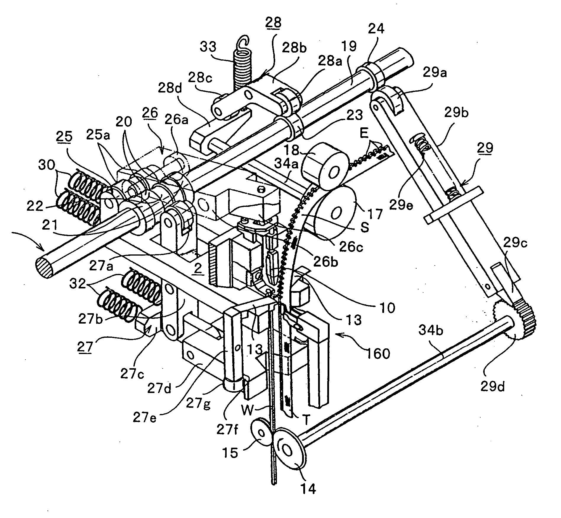
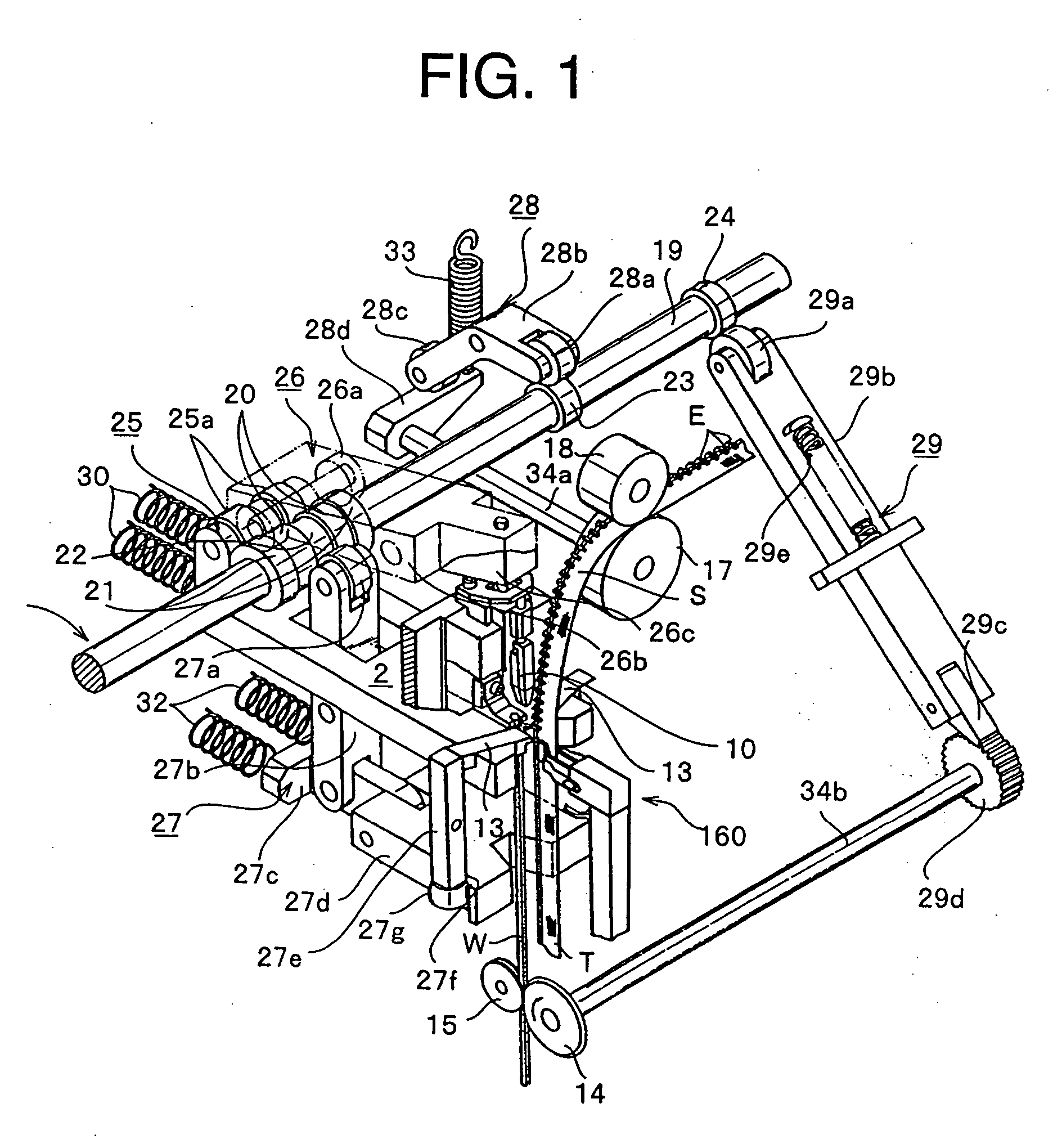
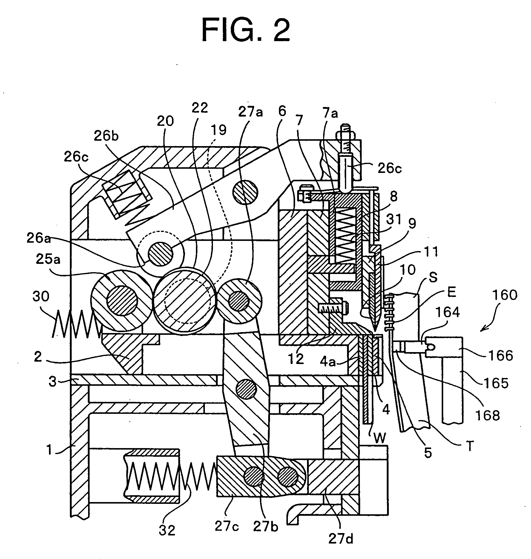
[0024]FIGS. 1 and 2 schematically show an example of major portions of a fastener stringer manufacturing apparatus of the invention. The structure of the indicated apparatus is substantially not different from the apparatus disclosed in the patent document 1. Thus, a following outline of the apparatus is based on the description of the above-mentioned publication. In these figures, a first ram 2 is supported on a base 1 through a ram guide 3 so as to be capable of reciprocating horizontally freely, and a cutting die 4 and a forming die 5 for molding a coupling head of an engaging element E into a mountain-like shape are provided on the front end of the first ram 2 in this order in an advancement direction of the first ram 2. The cutting die 4 has a through hole 4a through which a deformed linear material W for an engaging element passes, the linear ...


PUM

PropertyMeasurementUnit
thicknessaaaaaaaaaa
angleaaaaaaaaaa
nipping forceaaaaaaaaaa

Abstract

A continuous manufacturing apparatus for a fastener stringer, the apparatus comprising a tape guide capable of meeting sufficiently not only a conventional manufacturing speed but also acceleration of the manufacturing speed in recent years and generating no missing of an engaging element, wherein the tape guide includes a pair of nipping guide pieces which nip and guide a fastener tape, and urging means for elastically urging a core thread portion of an engaging element attaching edge portion of a fastener tape nipped by the nipping guide pieces toward a space between legs of an engaging element positioned and supported by a forming die, and wherein the core thread portion is pressed against a crotch of the engaging element securely with a predetermined pressing force by urging of the urging means and the engaging element is implanted firmly on the fastener tape under the state.

Description

BACKGROUND OF THE INVENTION [0001] 1. Field of the Invention [0002] The present invention relates to a manufacturing apparatus for a fastener stringer for successively attaching an engaging element for a slide fastener, the engaging element obtained by cutting an engaging element linear material having a substantially Y-shaped section forged preliminarily in the direction of its lateral section and then molding a coupling head of the engaging element into a mountain-like shape, to a fastener tape guided by a tape guide and supplied intermittently. More particularly, the invention relates to a continuous manufacturing apparatus for a fastener stringer, the apparatus having a tape guide which enables engaging elements to be attached to a fastener tape securely by eliminating attachment impossibility or attachment failure due to flipping of the engaging elements accompanied by acceleration of the manufacturing process. [0003] 2. Description of the Related Art [0004] As for this kind of...

Claims


Application Information

Patent Timeline
Patent Type & Authority Applications(United States)
IPC IPC(8): B32B37/00
CPCA44B19/46Y10T156/17Y10T156/1734A44B19/42
Inventor IAI, KENICHIROMORIOKA, KOITSU
Owner YKK CORP
Learn More