Mold for molding electric wire protection cap

a protection cap and electric wire technology, applied in the direction of dough shaping, manufacturing tools, coupling device connections, etc., can solve the problems of deterioration of the strength of the hinge b>65/b>, labor and man-hours,

Active Publication Date: 2007-11-13
YAZAKI CORP
View PDF10 Cites 2 Cited by
  • Summary
  • Abstract
  • Description
  • Claims
  • Application Information

AI Technical Summary

Benefits of technology

[0010]It is therefore an objective of the present invention to solve the above problem and to provide a mold for molding an electric wire protection cap, by which the locking lances do not necessitate being folded back, reliability of the locking lance is improved, and the molding can be securely carried out.

Problems solved by technology

However, in the conventional process for molding the electric wire protection cap 61 as described above, since the locking lances 63 are folded back after the molding, strength of the thin hinge 65 might be deteriorated, labor and man-hour is needed, and the thin hinge 65 is hardly filled with the molten resin upon the molding, resulting in that the strength of the hinge 65 might be deteriorated.

Method used


Image

  • Mold for molding electric wire protection cap
  • Mold for molding electric wire protection cap
  • Mold for molding electric wire protection cap

Examples


Embodiment Construction

[0036]In the following, preferred embodiments of the present invention will be explained with reference to the attached drawings.

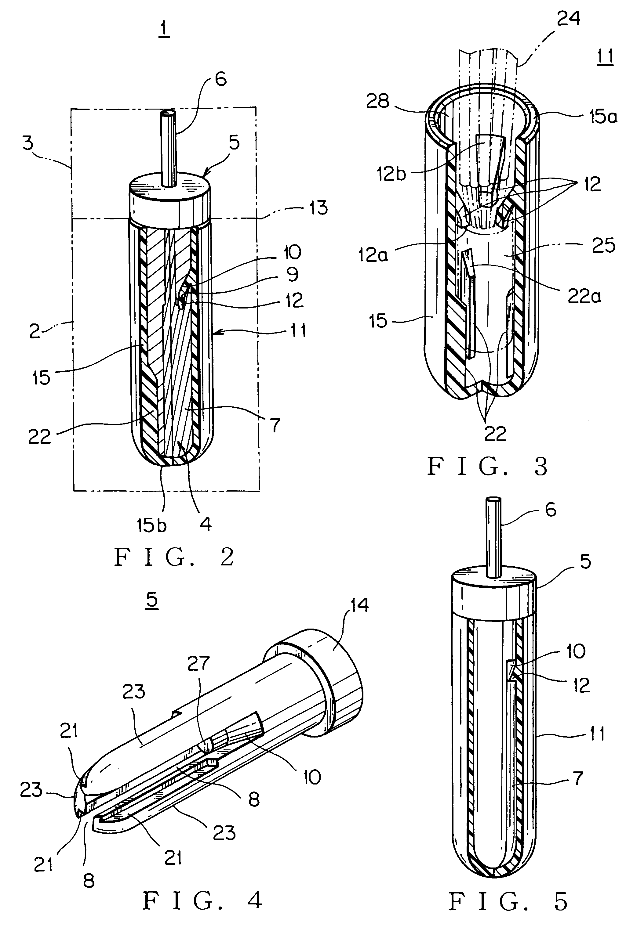
[0037]FIGS. 1 and 2 show a mold for molding an electric wire protection cap according to the present invention. FIG. 3 shows an electric wire protection cap molded by using the mold.

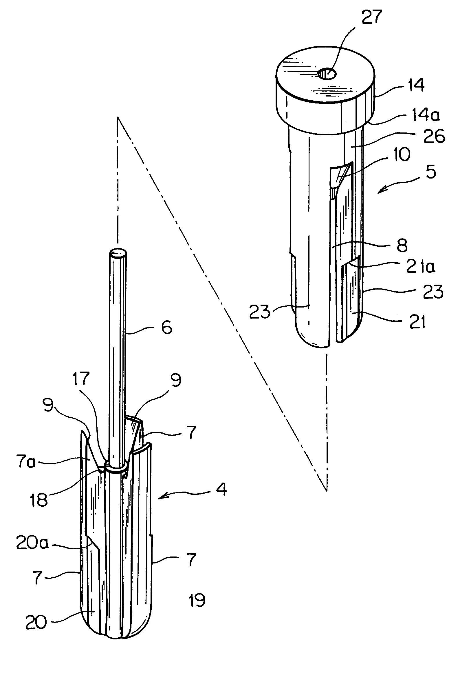
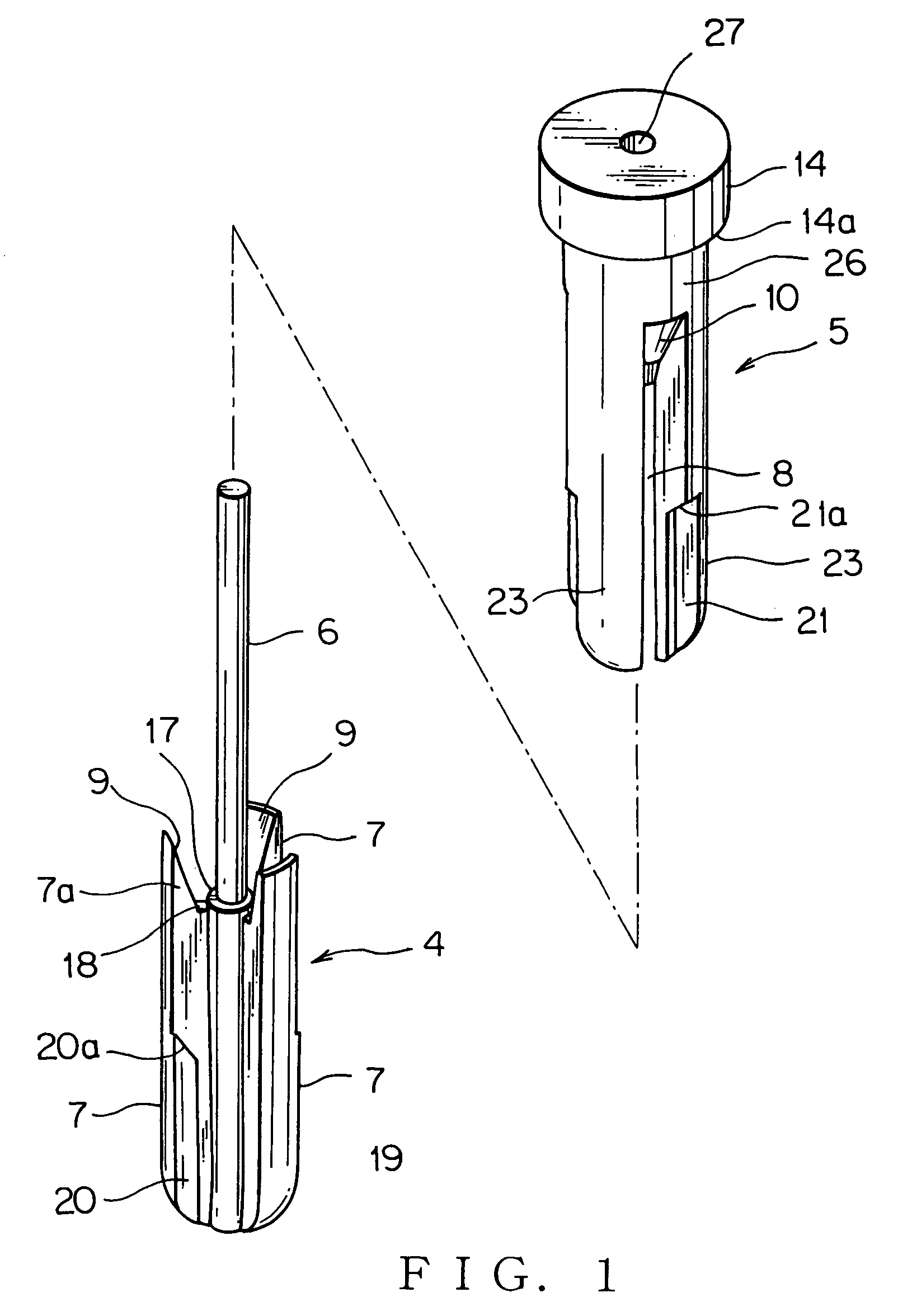
[0038]The mold 1 (shown in FIG. 2) includes as an outer mold a lower fixed mold 2 and an upper movable mold 3, both made of metal, the upper movable mold 3 includes as an inner mold a first mold member 4 and a second mold member 5, which are divided top and bottom, wherein the first mold member 4 is rotatable with a specific angle around a shaft 6 with respect to the second mold member 5 that is parted from the first mold member 4 upwardly, the first mold member 4 includes a plurality of (three in this example) projecting walls 7 in the radial direction, the second mold member 5 includes a plurality of (three in this example) notches 8 for fitting and receiving the respective p...


PUM

PropertyMeasurementUnit
rotation angleaaaaaaaaaa
circumferenceaaaaaaaaaa
flexibleaaaaaaaaaa

Abstract

The mold for molding an electric wire protection cap includes an outer mold and an inner mold for forming a cap body of the electric wire protection cap, the inner mold including a first mold member and a second mold member, the first mold member including a projecting wall and a shaft, the second mold member including a notch for fitting the projecting wall thereinto and a hole for passing the shaft therethrough, wherein a gap for forming a locking lance is formed between an end surface of the projecting wall and an end surface of the notch, the second mold member can come off along the shaft, and the first mold member is rotatable around the shaft.

Description

BACKGROUND OF THE INVENTION[0001](1) Field of the Invention[0002]The present invention relates to a mold for molding an electric wire protection cap for manufacturing the electric wire protection cap made of synthetic resin, which protects a joint part of electric wires in a wiring harness and so on from the outside.[0003](2) Description of the Related Art[0004]FIG. 9 shows an example of a conventional electric wire protection cap (referring to Japanese Patent Application Laid-Open No. H8-22847; pages 3-4 and FIG. 1).[0005]An electric wire protection cap 61 is for insulating and waterproof-protecting a joint part 66 of electric wires 67 in a wiring harness. The electric wire protection cap 61 is made of synthetic resin and integrally includes a cap body 62 having a bottom and a plurality of flexible locking lances 63 arranged in the cap body 62.[0006]Upon molding of the resin, each locking lances 63 is projectingly formed outward from an open end 64 of the cap body 62 through a thin...

Claims


Application Information

Patent Timeline
Patent Type & Authority Patents(United States)
IPC IPC(8): B29C33/44
CPCH01R43/24
Inventor TORII, CHIEKOYAMAMOTO, TAKAYUKIOZAWA, MASATO
Owner YAZAKI CORP
Why Eureka
Try Eureka