Connection apparatus for a wiping arm

a technology of wiping arm and connection device, which is applied in the direction of vehicle maintenance, vehicle cleaning, domestic applications, etc., can solve the problem of not being able to mount the wiper blade, and achieve the effect of at least minimizing the risk of mixing up the different wiper blades

Inactive Publication Date: 2012-06-12
ROBERT BOSCH GMBH
View PDF15 Cites 24 Cited by
  • Summary
  • Abstract
  • Description
  • Claims
  • Application Information

AI Technical Summary

Benefits of technology

[0009]A simple handling is cost-effectively achieved by the first connection part being releasable from and / or able to be connected to the second connection part by a rotation of at least one of the connection parts about the hinge axis by a releasing angle. In this manner it is possible without the aid of tools or without specialist knowledge to remove the wiper blade from the wiper arm and / or to connect said wiper blade and wiper arm together, whereby the assembly is simplified, in particular even for a non-professional. It is advantageous if the limit stop has a shoulder for determining the releasing angle. Moreover, it is advantageous if the releasing angle is between 5° and 50°, in particular between 20° and 40°, preferably between 20° and 30°, ideally approximately 25°, as in this manner a more secure retention of the connection device is ensured without having to make handling difficult when changing the wiper blade. In this connection, it is particularly advantageous if a limiting stop is provided, which in particular is formed by an edge or face of the receiver which prevents a rotation beyond the releasing angle. Ideally, the longitudinal shape of the receiver is dimensioned such that when releasing and / or connecting the connection parts it is able to receive the shoulder. In a simple embodiment, advantageously, the receiver is of groove-shaped configuration and comprises in particular two lateral walls and a base, which in particular is of substantially planar configuration. As a result, the first connection part is particularly suitable for being produced in an injection-molding process. In a development of the invention, it is provided that the first connection part has a spoiler wall, which forms the entire height of the first connection part and covers a spoiler side. In this manner, a particularly streamlined exterior is achieved and moreover a particularly attractive appearance is achieved. In a particularly simple, cost-effective and attractive manner, the securing means covers the first connection part in a substantially flush manner.
[0011]It is also conceivable to provide the limit stop of the securing means as well as a corresponding recess for receiving the limit stop as identification means. Thus the limit stops and / or recesses of two different connection devices may be differently formed and / or arranged in order to eliminate mixing up the wiper blades. For example, the limit stops of two different connection devices may be of different lengths and / or widths and the corresponding recesses accordingly designed with different depths and / or different widths. The variable arrangement of the limit stops of two different connection devices may, for example, be implemented by a variable bridge length.

Problems solved by technology

Thus, for example, it is not possible to mount the wiper blade which is on the driver side on the wiper arm which is on the passenger side.

Method used


Image

  • Connection apparatus for a wiping arm
  • Connection apparatus for a wiping arm
  • Connection apparatus for a wiping arm

Examples


Embodiment Construction

[0029]The same components and components with the same function are provided with the same reference numerals in the figures.

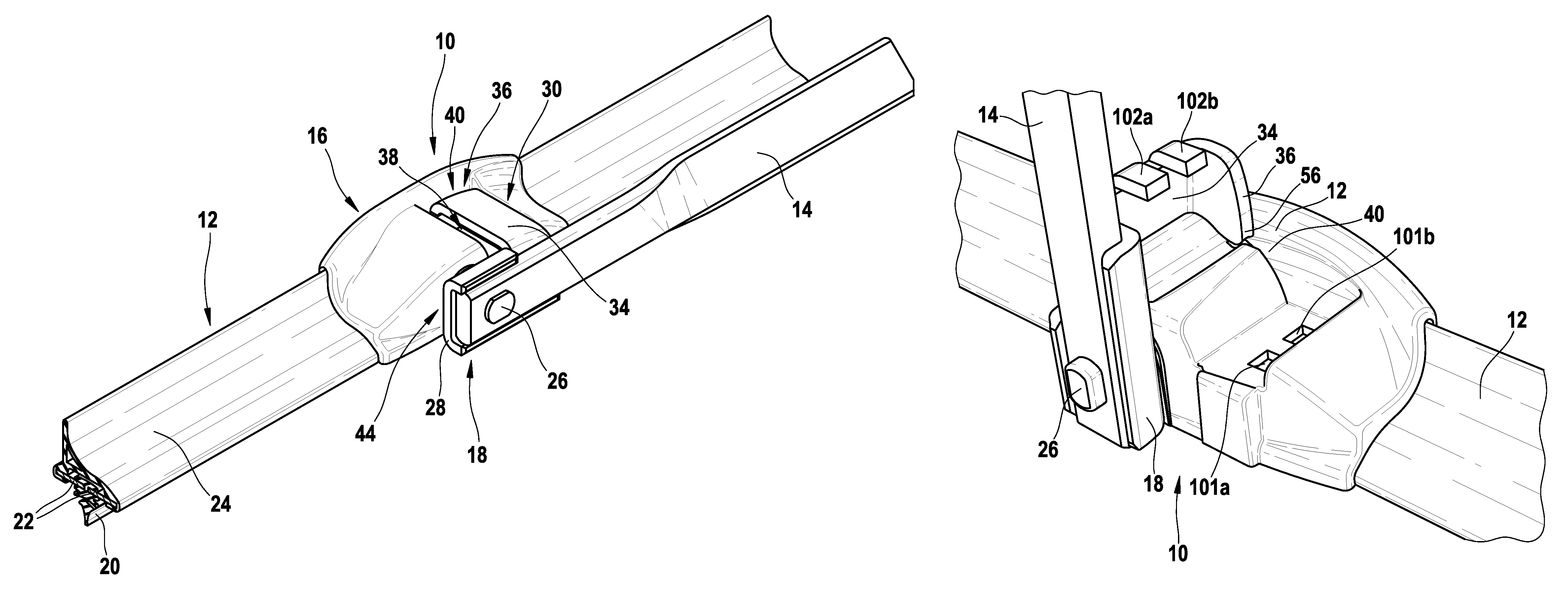
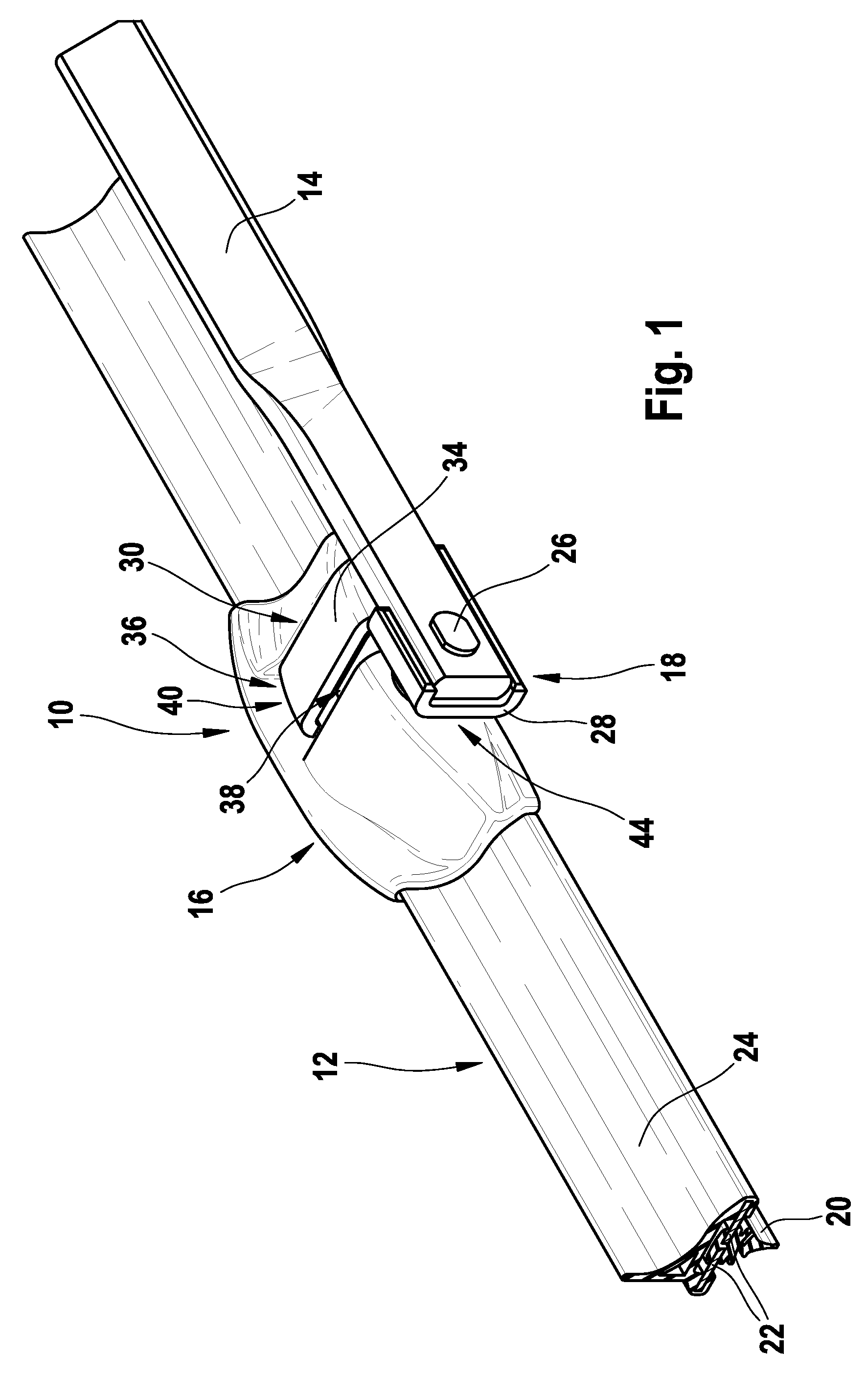
[0030]In FIG. 1 a connection device 10 is shown with a portion of a wiper blade 12 configured as a flat-bar wiper blade and a wiper arm 14. The connection device 10 shows substantially a first connection part 16 which is fastened to the wiper blade 12 as well as a second connection part 18 which is fastened to the wiper arm. The wiper blade 12 configured as flat-bar wiper blade substantially encompasses a wiper rubber 20 which is supported on a spring rail 22. For improving the flow characteristics on the side of the spring rail 22 remote from the wiper rubber 20, a spoiler 24 is fastened, in particular pushed onto the spring rail 22, which is formed from a rubber-elastic material. The first connection part 16 is fixedly connected to the spring rail 22, so that the wiper blade 12 is securely held on the first connection 16.

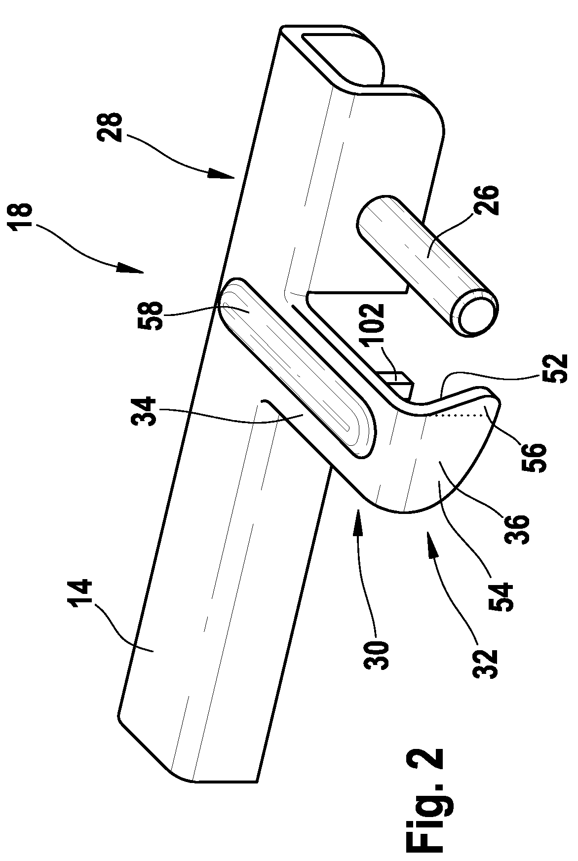
[0031]The wiper arm 14 bears at its f...


PUM


Abstract

The invention relates to a connection apparatus (10) for a wiper arm (14) and a wiper blade (12). The connection apparatus comprises a first and a second connection part. According to the invention, provision is made for the first connection part to have a first identification means and for the second connection part to have a second identification means which corresponds to the first identification means. The invention also comprises a system with two flat-bar wiper blades, with at least one first identification means being provided on at least one flat-bar wiper blade in order to distinguish between the two wiper blades.

Description

BACKGROUND OF THE INVENTION[0001]The invention relates to a connection device for a wiper arm and a wiper blade according to the preamble of claim 1, as well as a system consisting of two flat-bar wiper blades according to the preamble of claim 8.[0002]A connection device for a wiper arm and a wiper blade is already known from DE-A-102 30 457, which comprises a first connection part on the wiper blade side and a second connection part on the wiper arm side, which are arranged adjacent to one another in the operating position. The second connection part comprises a hinge element so that the wiper blade is pivotably connected to the wiper arm about a hinge axis, a securing means being provided so that the two connection parts engage in one another.[0003]Moreover, numerous connection devices for wiper arms and wiper blades are known, in which the connection part on the wiper arm side is arranged over the connection part on the wiper blade side.[0004]It is known to provide wiper blades ...

Claims


Application Information

Patent Timeline
Patent Type & Authority Patents(United States)
IPC IPC(8): B60S1/40
CPCB60S1/407B60S1/3863B60S1/32B60S1/40
Inventor DE BLOCK, PETERWINDMOLDERS, ERICVANGEEL, TOMBEELEN, HANS
Owner ROBERT BOSCH GMBH
Why Eureka
Try Eureka