Configurations and methods for thermal integration of LNG regasification and power plants

a technology of thermal integration and power plants, applied in the direction of liquefaction, machines/engines, lighting and heating apparatus, etc., can solve the problems of power plant inoperable, significant energy consumption, and most of these processes are typically limited, and achieve the effect of reducing water conten

Inactive Publication Date: 2012-06-12
FLUOR TECH CORP
View PDF5 Cites 81 Cited by
  • Summary
  • Abstract
  • Description
  • Claims
  • Application Information

AI Technical Summary

Benefits of technology

[0015]Various objects, features, aspects and advantages of the present invention will become more apparent from the following detailed description of preferred embodiments of the invention.

Problems solved by technology

However, such configurations often consume significant quantities of energy for compression / condensation of a refrigerant, and are typically not thermally coupled to an otherwise available source of cold.
While such plant configurations typically operate satisfactorily to at least some degree, various disadvantages remain.
While such configurations often advantageously integrate regasification of LNG with another, typically power generating process, various disadvantages remain.
For example, most of these processes are typically limited to cool the gas turbine intake air to 50° F.
(or even higher) to avoid water freezing of the intake air, which would create unsafe conditions or even making the power plant inoperable.
Therefore, improvements in power generation efficiency using LNG refrigeration content in known plants is typically limited by the cooling limit of the intake air temperature.
Moreover, while all or almost all of the currently known gas turbine air pre-cool methods tend to improve the power generation efficiencies in hot climate regions (e.g., in the tropics or sub-tropics), they are often not suitable in colder climate regions (e.g., northeastern parts of North America).
Even in relatively hot climate, such configurations provide very marginal efficiency benefits only in the summer months, with decreasing benefits in the winter seasons.
Therefore, while numerous processes and configurations for power plants with LNG utilization and / or regasification are known in the art, all of almost all of them suffer from one or more disadvantages.

Method used


Image

  • Configurations and methods for thermal integration of LNG regasification and power plants
  • Configurations and methods for thermal integration of LNG regasification and power plants
  • Configurations and methods for thermal integration of LNG regasification and power plants

Examples


Embodiment Construction

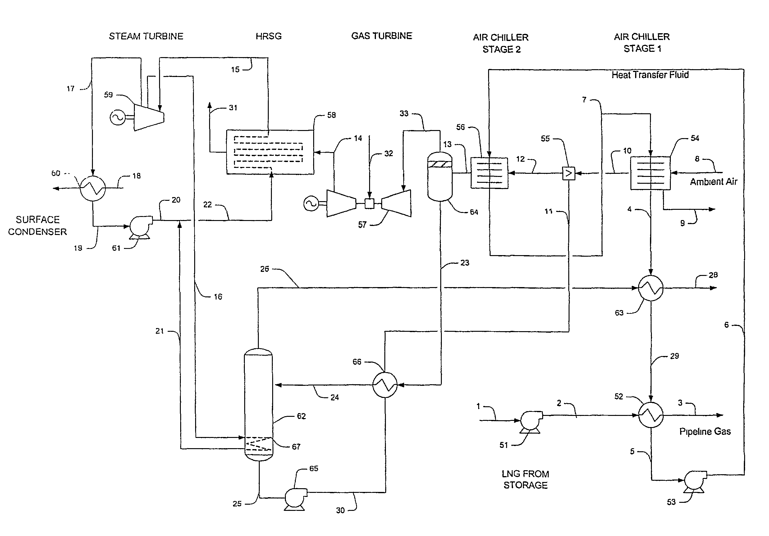
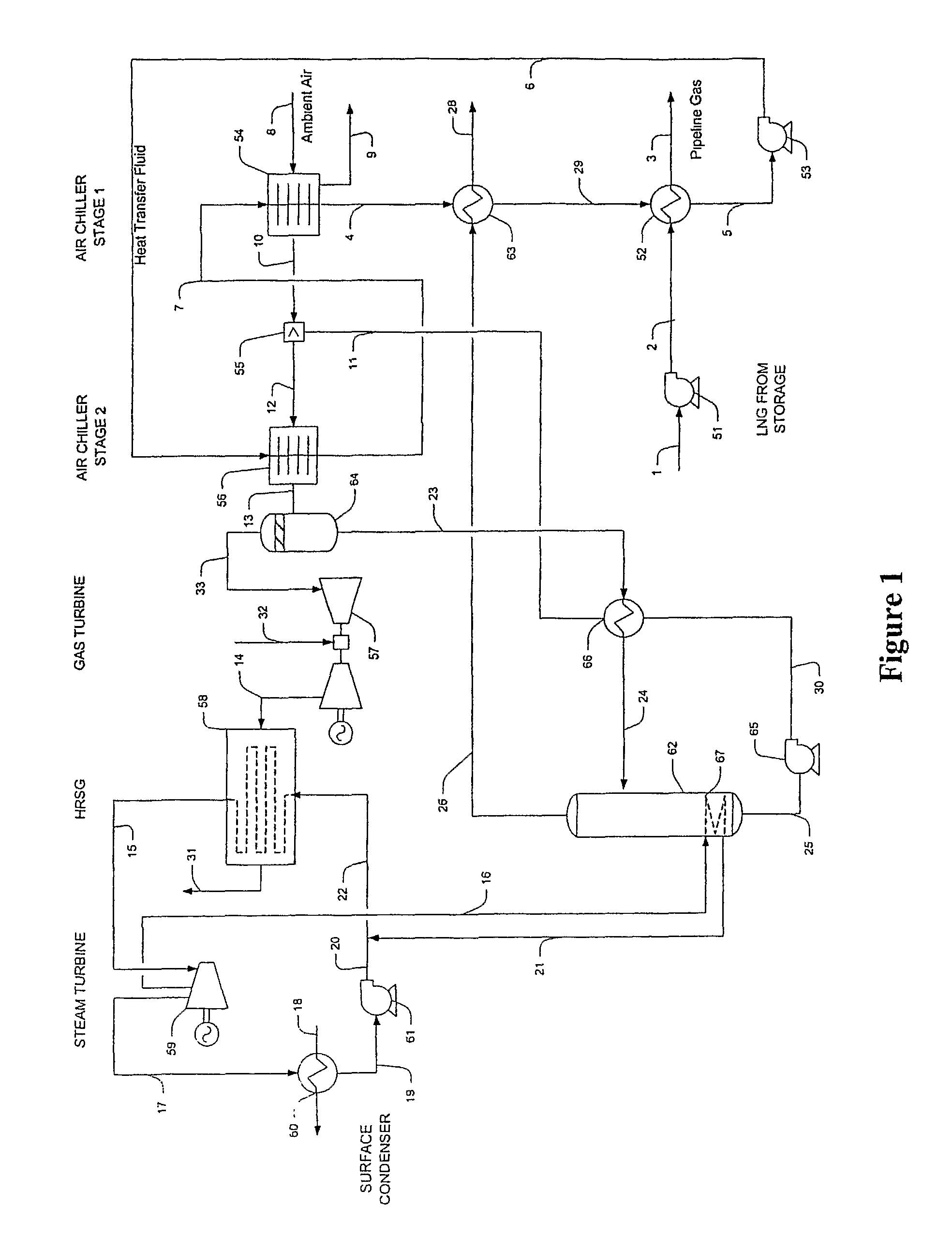
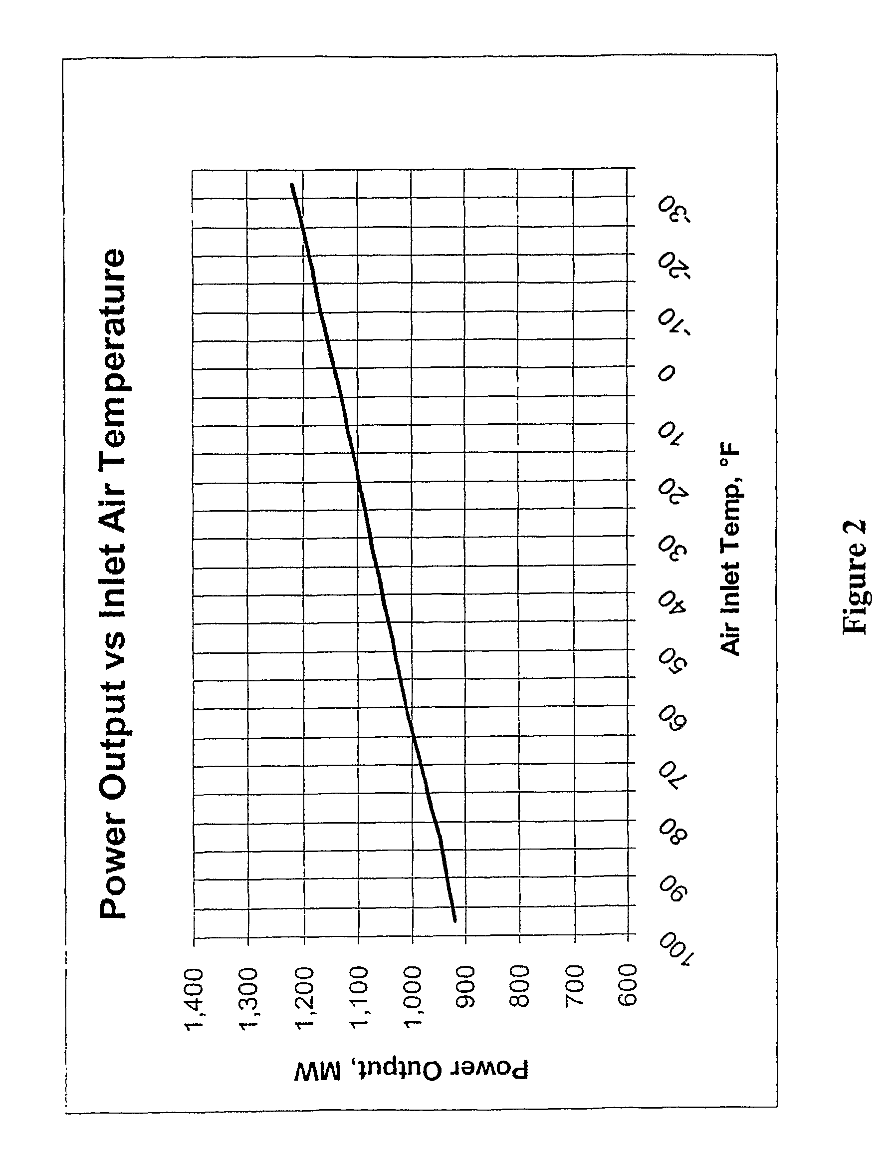
[0018]The inventor has discovered that subcooling of combustion turbine intake air in a power generating plant can be advantageously thermally coupled with an LNG regasification operation. Such configurations are characterized, among other desirable features, by improved and seasonally independent power output and by elimination of external energy requirements for LNG regasification.

[0019]In one particularly preferred aspect of processing LNG in a plant, LNG cold is utilized to increase the power generation output and efficiency of a gas turbine in a combined cycle power plant. Most typically, such configurations include a heat transfer fluid circuit that is employed to regasify LNG using the heat content of gas turbine inlet air, and a freeze point depressant solution circuit that prevents ice formation of subcooled (i.e., below 32° F.) inlet air, wherein the freeze point depressant solution is regenerated in the circuit using combustion heat of the gas turbine.

[0020]One exemplary ...


PUM


Abstract

Contemplated plants integrate regeneration of a freeze point depressant with LNG regasification and a power cycle. Most preferably, the plant is a combined cycle plant in which heat for reboiling the regenerator is provided by the steam cycle, and in which LNG refrigeration content is used to condense steam from the regenerator and to further subcool intake air for a combustion turbine.

Description

[0001]This application claims priority to our copending U.S. provisional patent application with the Ser. No. 60 / 667,182, which was filed Mar. 30, 2005.FIELD OF THE INVENTION[0002]The field of the invention is power generation in LNG regasification facilities, and especially thermal integration of regasification in a combined cycle power plant using intake air chilling.BACKGROUND OF THE INVENTION[0003]Air intake chilling for combustion turbines is well known in the art and various cold sources have been employed. For example, numerous evaporative chillers with and without intermediate heat transfer fluids are described in U.S. Pat. No. 6,457,315. However, such configurations often consume significant quantities of energy for compression / condensation of a refrigerant, and are typically not thermally coupled to an otherwise available source of cold.[0004]In other known configurations, refrigeration content of liquefied natural gas (LNG) is utilized to chill intake air, wherein the air...

Claims


Application Information

Patent Timeline
Patent Type & Authority Patents(United States)
IPC IPC(8): F02C1/00
CPCF02C3/22F02C7/22Y02E20/16Y02E20/18
Inventor MAK, JOHN
Owner FLUOR TECH CORP
Why Eureka
Try Eureka