Continuous casting sealing method

a sealing method and casting technology, applied in the direction of casting parameters measurement/indication devices, manufacturing tools,foundry moulding apparatus, etc., can solve the problems of furnaces with several limitations, hard alpha defects in cast titanium, and inability to continue casting, etc., to achieve convenient handling

Active Publication Date: 2012-06-12
HOWMET AEROSPACE INC
View PDF26 Cites 18 Cited by
  • Summary
  • Abstract
  • Description
  • Claims
  • Application Information

AI Technical Summary

Problems solved by technology

In either case, contamination of the furnace chamber with oxygen or nitrogen, which react with molten titanium, may cause hard alpha defects in the cast titanium.
Although functional, such furnaces have several limitations.
Thus, such furnaces allow continuous melting operations but do not allow continuous casting.
Controlled cooling of the cast top, known as a “hot top”, can reduce these cavities, but the hot top is a time-consuming process which reduces productivity.
The top portion of the cast containing shrinkage or pipe cavities is unusable material which thus leads to a yield loss.
Moreover, there is an additional yield loss due to the dovetail at the bottom of the cast that attaches to the withdrawal ram.

Method used


Image

  • Continuous casting sealing method
  • Continuous casting sealing method
  • Continuous casting sealing method

Examples


Embodiment Construction

[0048]At the outset, it should be appreciated that like drawing numbers on different drawing views identify identical, or functionally similar, structural elements of the invention. While the present invention is described with respect to what is presently considered to be the preferred embodiments, it is to be understood that the invention as claimed is not limited to the disclosed aspects.

[0049]Unless defined otherwise, all technical and scientific terms used herein have the same meaning as commonly understood to one of the ordinary skill in the art to which this invention belongs. Although any methods, devices or materials similar or equivalent to those described herein can be used in the practice or testing of the invention, the preferred methods, devices, and materials are now described.

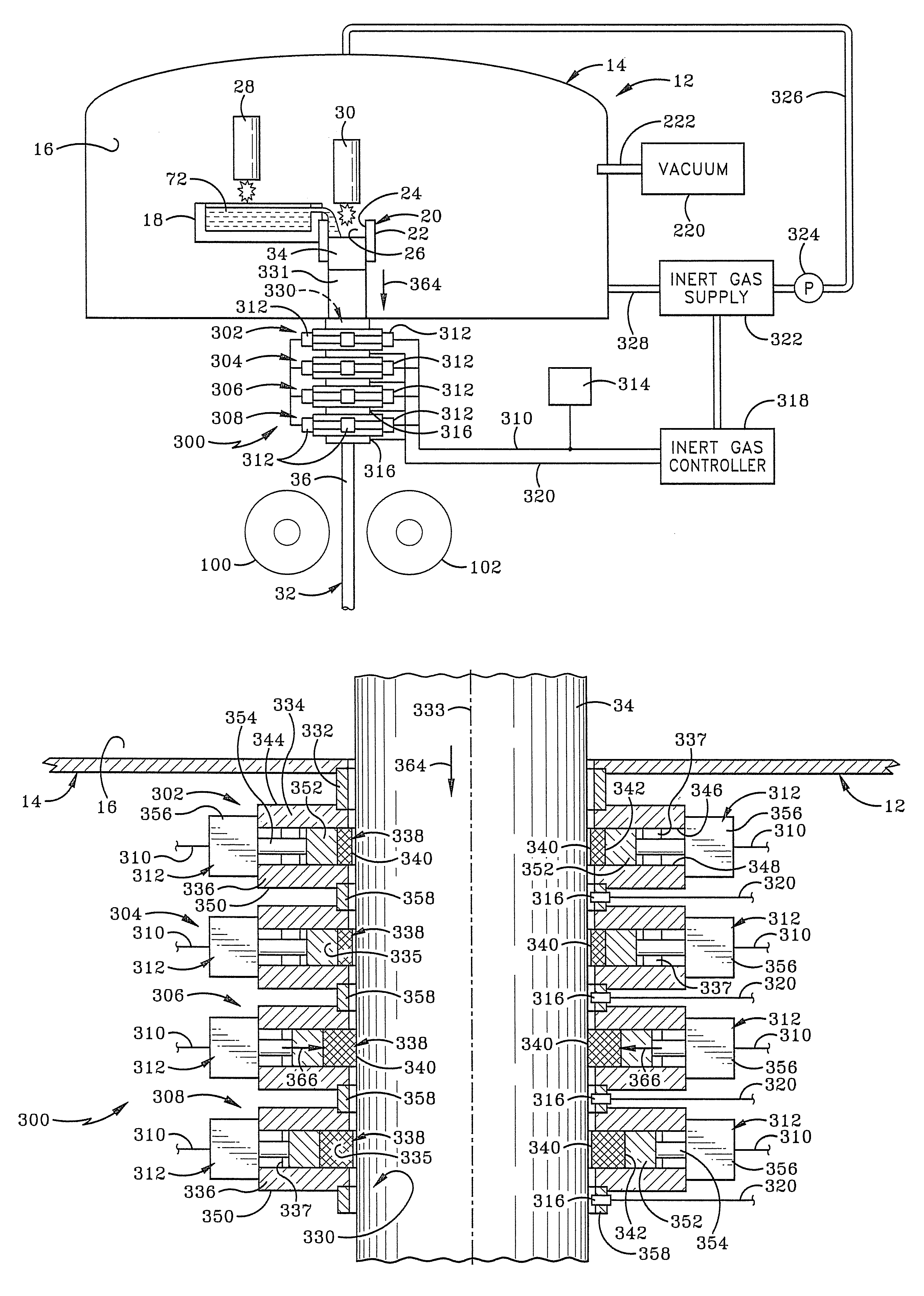
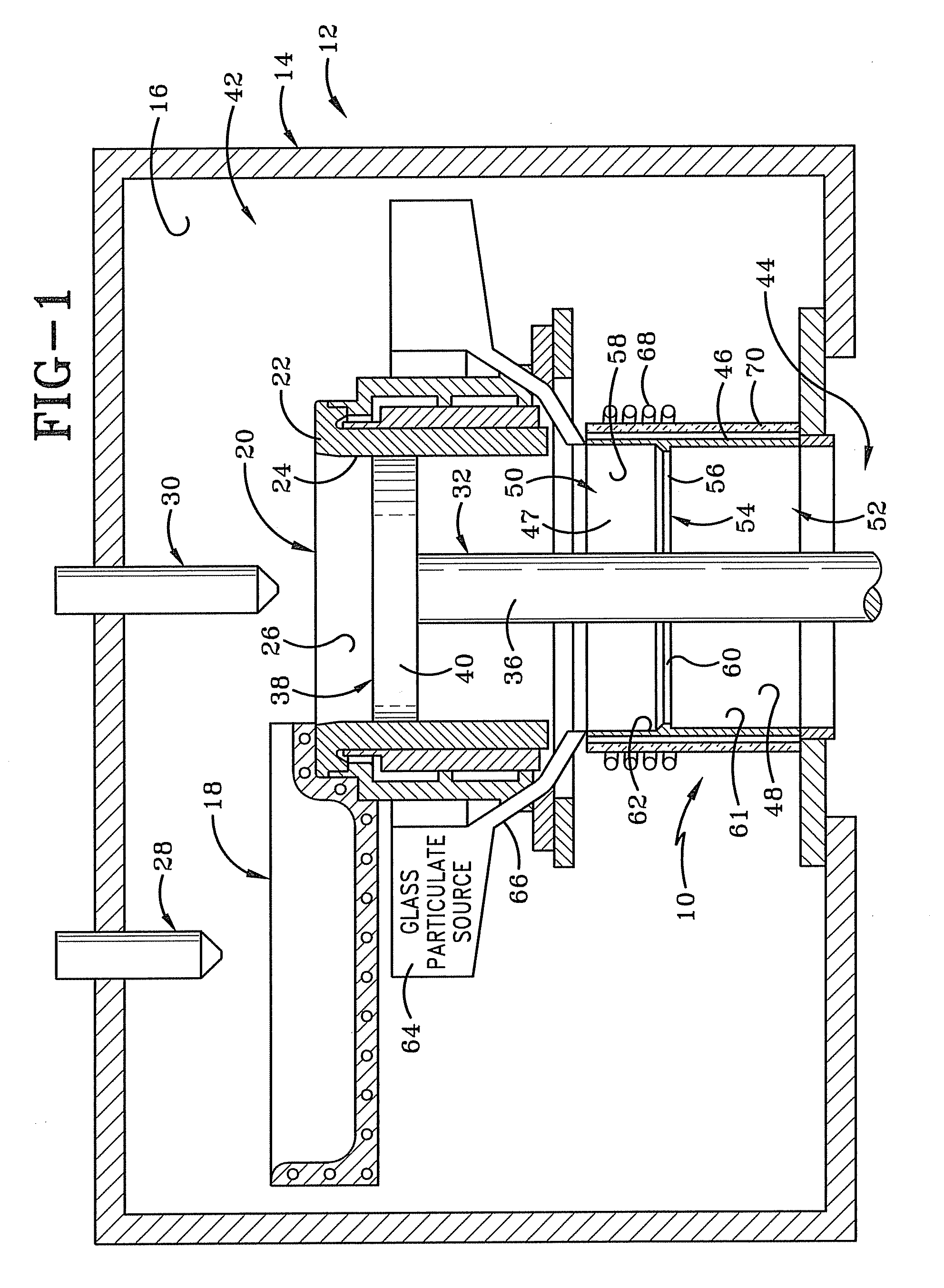
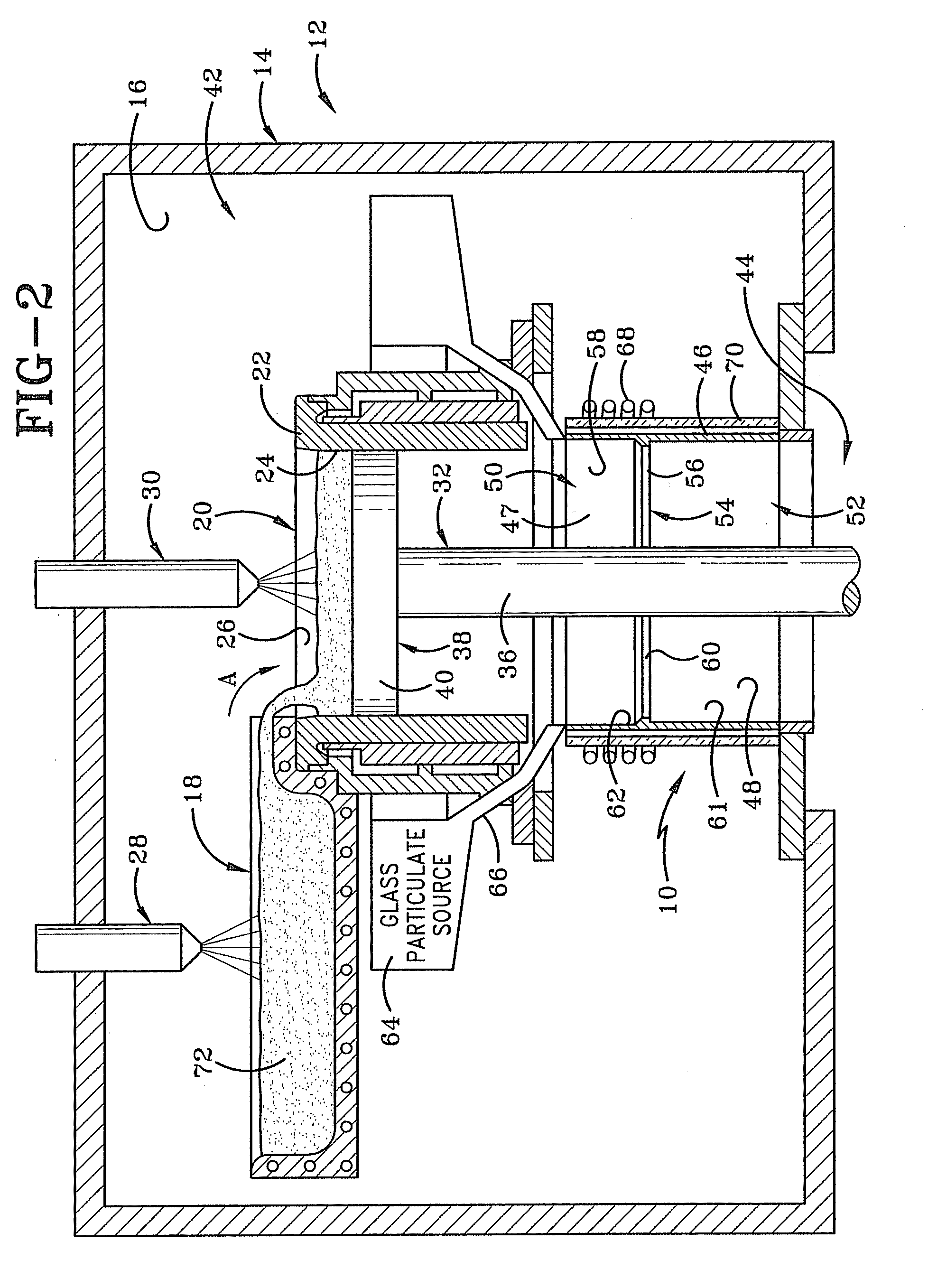
[0050]The seal of the present invention is indicated generally at 10 in FIGS. 1-5 in use with a continuous casting furnace 12. Furnace 12 includes a chamber wall 14 which encloses a melting cham...


PUM

PropertyMeasurementUnit
temperatureaaaaaaaaaa

Abstract

A casting furnace for manufacturing a metal casting comprises an interior chamber and a secondary chamber through which the metal casting passes from the interior chamber into external atmosphere. A seal along the secondary chamber surrounds and seals against the metal casting to separate the interior chamber from the external atmosphere in a manner which allows for an extended period of continuous casting. A force producing mechanism typically forces the seal against the metal casting. Multiple seals may be used sequentially to increase the duration of the sealing capability and the continuous casting process.

Description

CROSS REFERENCE TO RELATED APPLICATIONS[0001]This application is a continuation-in-part of U.S. patent application Ser. No. 12 / 283,226, filed Sep. 10, 2008, now U.S. Pat. No. 7,926,548 , which is a continuation-in-part of U.S. patent application Ser. No. 11 / 799,574, filed May 2, 2007, now U.S. Pat. No. 7,484,549, which is a continuation-in-part of U.S. patent application Ser. No. 11 / 433,107, filed May 12, 2006, now U.S. Pat. No. 7,484,548, which is a continuation-in-part of U.S. patent application Ser. No. 10 / 989,563, filed Nov. 16, 2004, now U.S. Pat. No. 7,322,397; the contents of the applications are entirely incorporated herein by reference.BACKGROUND OF THE INVENTION[0002]1. Technical Field[0003]The invention relates generally to the continuous casting of metals. More particularly, the invention relates to the protection of reactionary metals from reacting with the atmosphere when molten or at elevated temperatures. Specifically, the invention relates to pressurized seals which...

Claims


Application Information

Patent Timeline
Patent Type & Authority Patents(United States)
IPC IPC(8): B22D11/00
CPCB22D11/007B22D11/04B22D11/055B22D11/07B22D11/08B22D11/10B22D11/108B22D11/113B22D11/141B22D11/06
Inventor JACQUES, MICHAEL P.YU, KUANG-O
Owner HOWMET AEROSPACE INC
Why Eureka
Try Eureka