Semiconductor device and plural semiconductor elements with suppressed bending

a semiconductor and semiconductor technology, applied in semiconductor devices, semiconductor/solid-state device details, electrical devices, etc., can solve the problems of damage to the extended portion of the semiconductor elements positioned on the upper side, normal wire bonding is not performed,

Inactive Publication Date: 2012-06-12
SOCIONEXT INC
View PDF41 Cites 9 Cited by
  • Summary
  • Abstract
  • Description
  • Claims
  • Application Information

AI Technical Summary

Benefits of technology

[0024]Thus, with a semiconductor element employing a configuration of layering semiconductor elements, in the event of performing wire bonding of the semiconductor element positioned on the upper side to the electrode terminal, in order to prevent deformity of the extended portion of the semiconductor elements, various proposals have been made.

Problems solved by technology

In such a case, if wire bonding is attempted to the electrode terminal of the semiconductor element positioned on the upper side, the extended portion of the semiconductor element warps (bends toward the bottom side, supporting base side), and since sufficient pressure is not applied, normal wire bonding is not performed.
Also, if a greater pressure is applied, there may be cases wherein the extended portion of the semiconductor elements positioned on the upper side is damaged.

Method used


Image

  • Semiconductor device and plural semiconductor elements with suppressed bending
  • Semiconductor device and plural semiconductor elements with suppressed bending
  • Semiconductor device and plural semiconductor elements with suppressed bending

Examples


first embodiment

(First Embodiment)

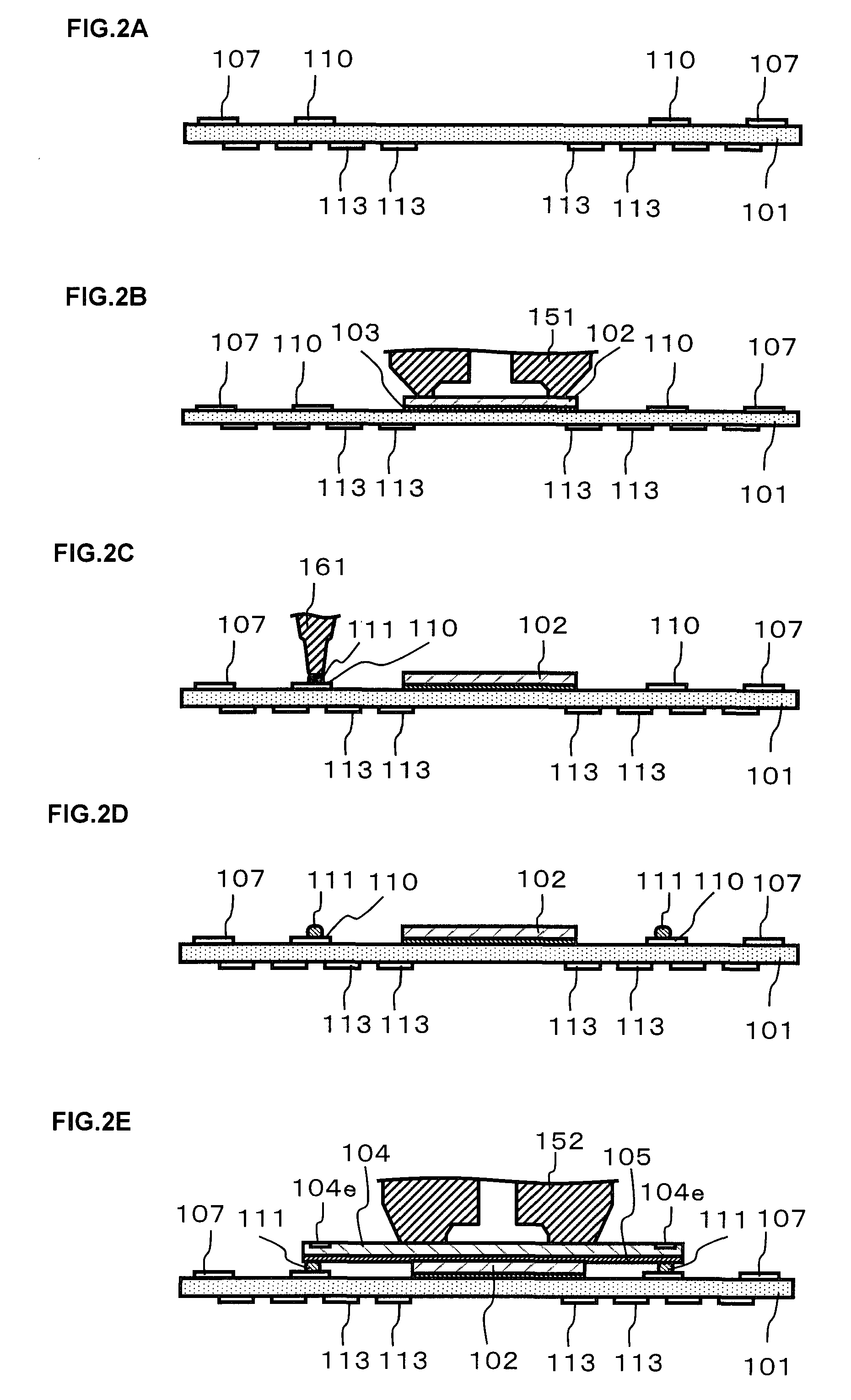
[0090]A first embodiment of the semiconductor device accord will be described with reference to FIGS. 1A through 9B.

[0091]The semiconductor device according to the present embodiment comprises a first semiconductor element which is mounted on a wiring board serving as a supporting base in a face-up state, with an external connection electrode terminal of the first semiconductor element being connected to an electrode terminal on the wiring board with a wire bonding method; and a second semiconductor element which is mounted on the first semiconductor element in a face-up state, with an external connection electrode terminal of the second semiconductor element being connected to an electrode terminal on the wiring board with a wire bonding method.

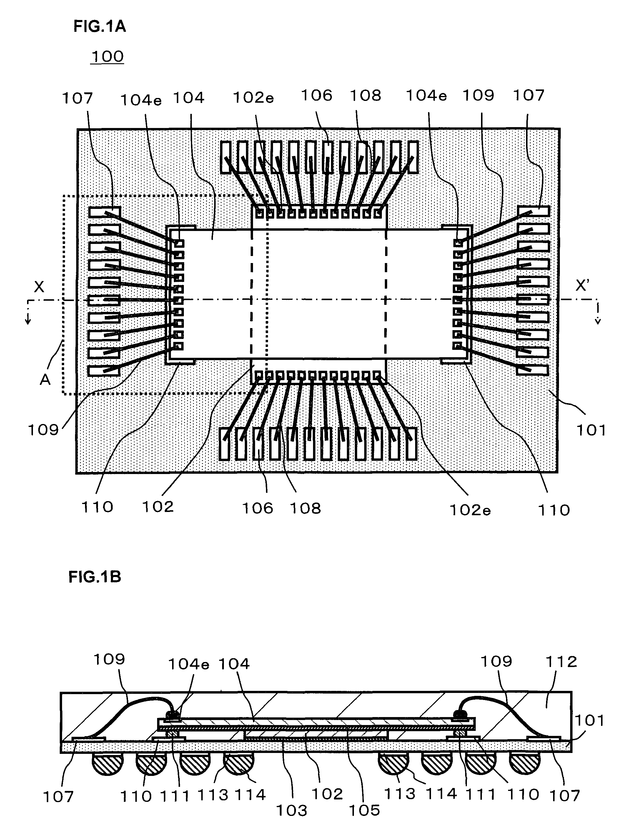
[0092]A semiconductor device 100 according to the first embodiment is shown in FIGS. 1A and 1B.

[0093]FIG. 1A shows a plan view of the semiconductor device 100, and FIG. 1B shows an X-X′ cross-section of FIG. 1A. Note that i...

second embodiment

(Second Embodiment)

[0231]A second embodiment of the semiconductor device according will be described with reference to FIGS. 9A through 13B.

[0232]The semiconductor element according to the present embodiment is mounted in a face-down (flip-chip) state on a wiring board which is a supporting base, and comprises a first semiconductor element wherein external connection bump electrodes thereof are connected to electrode terminals on the wiring board, and a second semiconductor element which is mounted on the first semiconductor element in a face-up state, wherein an electrode terminal pad thereof is connected to the electrode terminals on the wiring board with a wire bonding method.

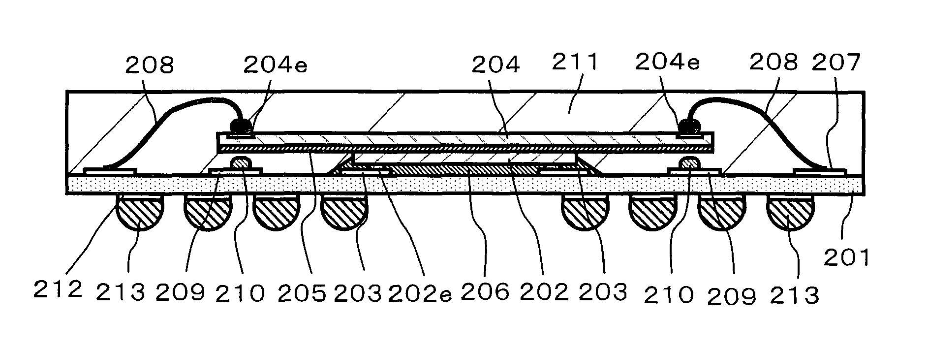
[0233]A semiconductor device 200 according to the second embodiment is shown in FIGS. 9A and 9B.

[0234]FIG. 9A shows a flat surface of the semiconductor device 200, and FIG. 9B shows an X-X′ cross-section of FIG. 9A. Note that in FIG. 9A, display of a resin sealing portion is omitted, and the external form th...

third embodiment

(Third Embodiment)

[0288]A third embodiment of the semiconductor element will be described with reference to FIGS. 14A through 22B.

[0289]The semiconductor device according to the third embodiment comprises a first semiconductor element which is mounted on a wiring board serving as a supporting base in a face-up state, with an external connection electrode terminal of the first semiconductor element being connected to an electrode terminal on the wiring board with a wire bonding method; a second semiconductor element which is mounted on the first semiconductor element in a face-up state, with an external connection electrode terminal of the second semiconductor element being connected to an electrode terminal on the wiring board with a wire bonding method; and a third semiconductor element which is mounted on the second semiconductor element in a face-up state, with an external connection electrode terminal of the third semiconductor element being connected to an electrode terminal on...


PUM


Abstract

A semiconductor device includes a supporting base whereupon an electrode terminal is placed; an intermediate member mounted on said supporting base; a semiconductor element, a portion thereof being supported with said intermediate member, and placed on said supporting base; and a convex-shaped member which corresponds to the electrode terminal of said semiconductor element and placed on said supporting base or said intermediate member; wherein the electrode terminal of said semiconductor element and the electrode terminal of said supporting base are connected with a bonding wire.

Description

CROSS REFERENCE TO RELATED APPLICATIONS[0001]This application is based upon and claims the benefit of priority from the prior Japanese Patent Application No. 2007-219278 filed on Aug. 27, 2007, the entire contents of which are incorporated herein by reference.BACKGROUND[0002]1. Technical Field[0003]The embodiments relate to a semiconductor device including plural semiconductor elements and a manufacturing method thereof.[0004]2. Description of the related art[0005]As electronic equipment has increased in functionality and decreased in size, semiconductor devices such as the semiconductor integrated circuit device installed in such electronic equipment are also desired to have higher functionality, higher operating speed, and further, smaller size and lighter weight.[0006]Therefore, with the semiconductor device, plural semiconductor elements are mounted so as to be layered on a supporting base (supporting board) such as a circuit board.[0007]Thus, a configuration having plural semic...

Claims


Application Information

Patent Timeline
Patent Type & Authority Patents(United States)
IPC IPC(8): H01L23/48H01L23/02H01L29/40H01L23/52H01L23/34
CPCH01L24/29H01L24/32H01L24/743H01L23/3128H01L23/49575H01L24/05H01L24/06H01L24/48H01L24/49H01L24/73H01L24/75H01L24/83H01L24/85H01L24/92H01L25/0657H01L2225/06575H01L2924/01004H01L2924/01005H01L2924/01013H01L2924/01014H01L2924/01015H01L2924/01028H01L2924/01029H01L2924/01031H01L2924/01033H01L2924/01046H01L2924/01047H01L2924/0105H01L2924/01078H01L2924/01079H01L2924/01082H01L2924/014H01L2924/07802H01L2924/09701H01L2924/10329H01L2924/14H01L2924/15311H01L2924/19041H01L2924/19043H01L2924/20751H01L2924/20752H01L2924/30107H01L2224/32145H01L2924/01006H01L2924/0665H01L2924/0132H01L2924/0133H01L2224/83444H01L2224/83455H01L2924/15787H01L2924/15788H01L2224/29111H01L2224/48227H01L2224/8314H01L2224/48799H01L2924/12041H01L2224/05553H01L21/565H01L24/45H01L24/78H01L24/81H01L2224/0401H01L2224/04042H01L2224/05554H01L2224/05556H01L2224/06136H01L2224/1134H01L2224/1308H01L2224/13144H01L2224/16225H01L2224/2919H01L2224/32225H01L2224/32245H01L2224/45015H01L2224/45124H01L2224/45139H01L2224/45144H01L2224/45147H01L2224/48091H01L2224/48247H01L2224/48465H01L2224/48471H01L2224/48479H01L2224/48599H01L2224/48699H01L2224/49171H01L2224/4943H01L2224/4945H01L2224/73204H01L2224/73257H01L2224/73265H01L2224/78301H01L2224/81203H01L2224/81801H01L2224/83099H01L2224/83191H01L2224/83192H01L2224/8385H01L2224/85045H01L2224/85051H01L2224/85181H01L2224/85191H01L2224/85205H01L2224/85951H01L2224/85986H01L2224/92247H01L2225/0651H01L2225/06555H01L2225/06562H01L2924/00014H01L2224/85186H01L2924/07025H01L2924/00H01L2924/3512H01L2924/0695H01L2924/00012H01L2224/85203H01L2924/181H01L2924/10161H01L2224/75745H01L2224/4554H01L2224/85399H01L2224/05599
Inventor NISHIMURA, TAKAO
Owner SOCIONEXT INC
Why Eureka
Try Eureka