Automotive battery charging system tester

a charging system and automotive technology, applied in the direction of testing electric installations on transportation, transportation and packaging, instruments, etc., can solve the problems of perceived battery failure, cumbersome testing, and difficult handling

Inactive Publication Date: 2012-06-12
MIDTRONICS
View PDF720 Cites 38 Cited by
  • Summary
  • Abstract
  • Description
  • Claims
  • Application Information

AI Technical Summary

Problems solved by technology

With the advent of accurate battery testing, it has become apparent that in some instances the battery in the vehicle may be good, and a problem related to the battery charging system is the cause of the perceived battery failure.
Such a test is cumbersome as the equipment is large and difficult to handle.
Further, it is difficult, particularly with compact engines, to reach the alternator output cable.
Further, in some cases, the amp clamp may not fit around the output cable.
It is also very easy to place the amp clamp around the wrong cable causing a false test.

Method used


Image

  • Automotive battery charging system tester
  • Automotive battery charging system tester
  • Automotive battery charging system tester

Examples


Embodiment Construction

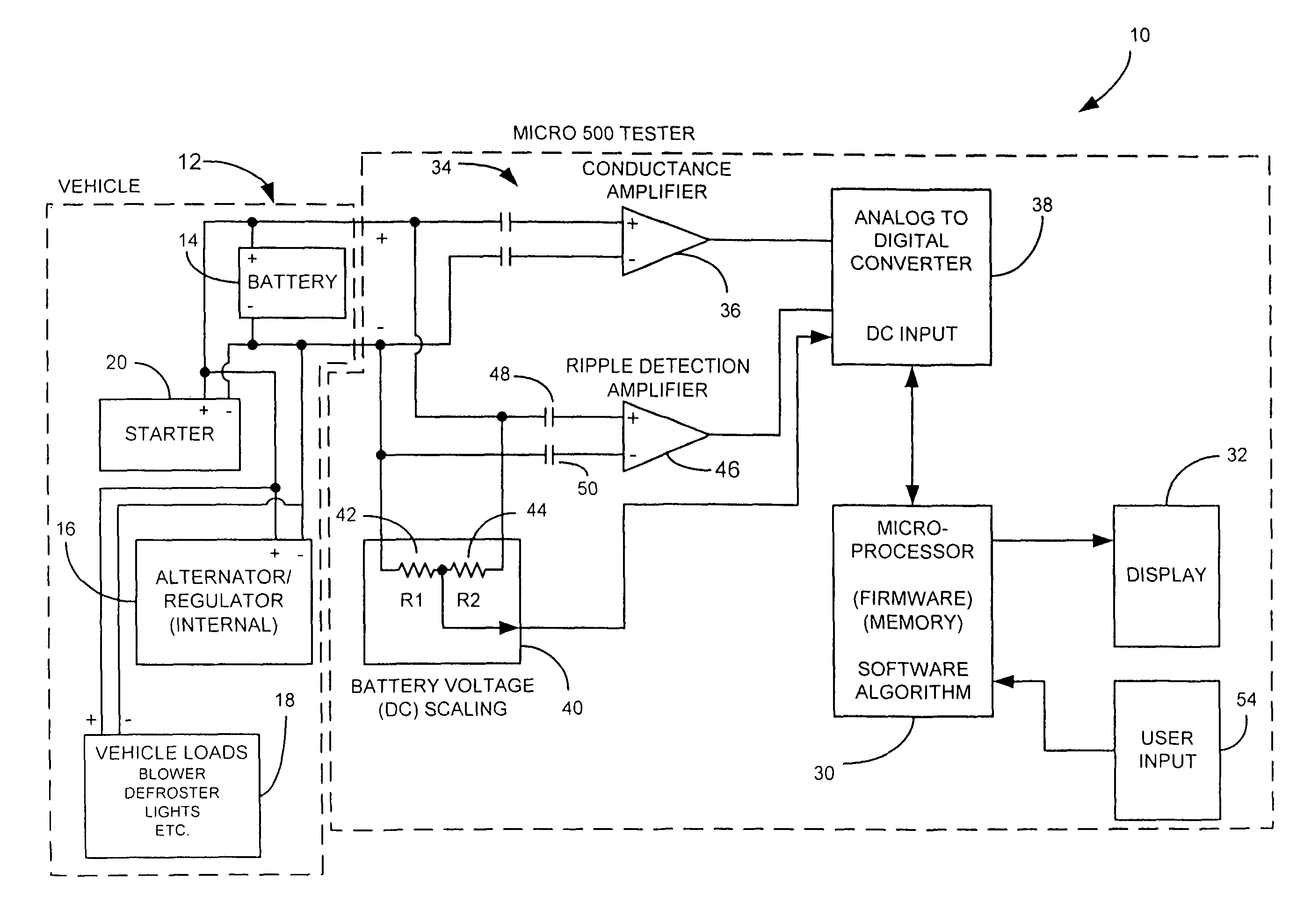
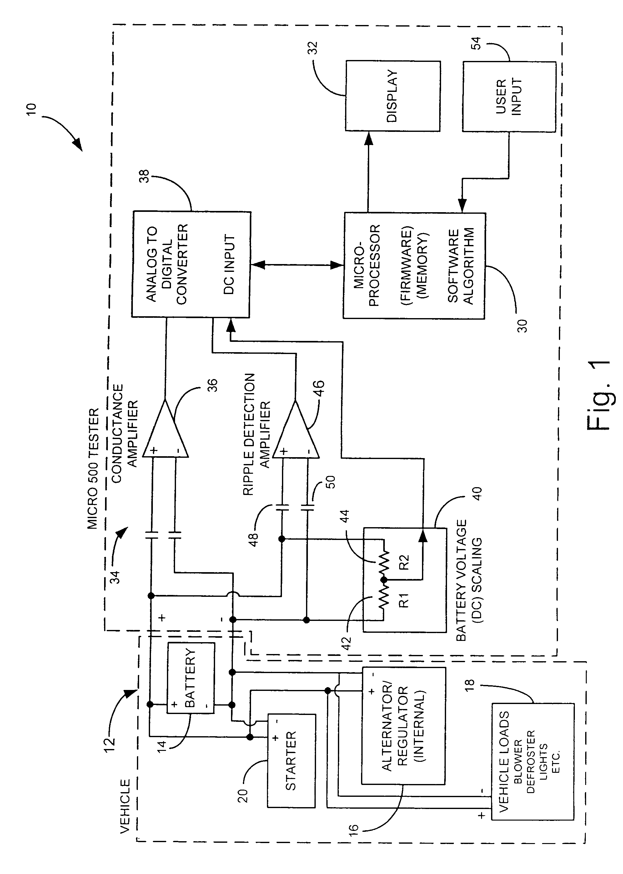
[0017]FIG. 1 is a simplified block diagram of a battery charging system tester 10 in accordance with one embodiment of the present invention coupled to a vehicle 12. Vehicle 12 includes a battery 14 having positive and negative terminals, an alternator with internal regulator 16, various vehicle loads 18, and a starter motor 20. In operation, battery 14 provides power to starter 20 and vehicle loads 18 when the engine in vehicle 12 is not running. When the engine in vehicle 12 is running, alternator 16 is used to power vehicle loads 18 and provide a charging current to battery 14 to maintain the charge of battery 14.

[0018]Charging system tester 10 includes a microprocessor 30 which controls operation of tester 10 and provides instructions and test result information to an operator through, for example, a display 32. Tester 10 includes a battery testing section 34 which is illustrated generally as conductance amplifier 1. Section 34 operates in accordance with, for example, the condu...


PUM

PropertyMeasurementUnit
total voltageaaaaaaaaaa
charging voltageaaaaaaaaaa
ripple voltageaaaaaaaaaa

Abstract

An automotive battery charging system tester for testing the charging system of an automotive vehicle includes AC and DC voltage measurement circuits and a microprocessor controlled testing sequence. The microprocessor is used to perform a series of tests and to instruct an operator to perform steps associated with performing those tests. Through the application of various loads at various engine speeds, the tester is capable of identifying faults in the battery charging system including a bad battery, problems in the alternator or associated electronics, and problems in the starting system.

Description

[0001]The present application is a Continuation-In-Part of application Ser. No. 10 / 098,741, filed Mar. 14, 2002 which is a Continuation-In-Part of U.S. patent application Ser. No. 09 / 575,629, filed May 22, 2000, now U.S. Pat. No. 6,445,158, which is a Continuation-In-Part of Ser. No. 09 / 293,020, filed Apr. 16, 1999, now U.S. Pat. No. 6,351,102; application Ser. No. 09 / 575,629 is also a Continuation-In-Part of Ser. No. 09 / 426,302, filed Oct. 25, 1999, now U.S. Pat. No. 6,091,245; which is a Divisional of Ser. No. 08 / 681,730, filed Jul. 29, 1996, now U.S. Pat. No. 6,051,976, the contents of which are hereby incorporated by reference in their entirety.BACKGROUND OF THE INVENTION[0002]The present invention relates to devices for testing an automotive vehicle. More specifically, the present invention relates to a battery charging system tester for an automotive vehicle.[0003]Automotive vehicles include a storage battery for operating electronics in the vehicle and using an electric start...

Claims


Application Information

Patent Timeline
Patent Type & Authority Patents(United States)
IPC IPC(8): G01N27/416G01R31/00G01R31/34G01R31/36
CPCG01R31/007G01R31/343G01R31/3631G01R31/3641G01R31/3648G01R31/3651G01R31/3662G01R31/3668G01R31/3675G01R31/3693G01R31/3647G01R31/367G01R31/374G01R31/379G01R31/386G01R31/3865G01R31/389
Inventor BERTNESS, KEVIN I.TROY, MICHAEL E.
Owner MIDTRONICS
Why Eureka
Try Eureka