Stator winding having cascaded end loops

a technology of cascaded end loops and windings, which is applied in the direction of windings, dynamo-electric components, magnetic circuit shapes/forms/construction, etc., can solve the problems of increasing the complexity of winding the stator, increasing the difficulty of manufacturing the stators, and disadvantages of the stators

Inactive Publication Date: 2005-04-19
BORGWARNER INC
View PDF80 Cites 81 Cited by
  • Summary
  • Abstract
  • Description
  • Claims
  • Application Information

AI Technical Summary

Benefits of technology

[0010]The cascaded winding pattern in accordance with the present invention advantageously does not require the complex interlaced winding process or the hairpin conductors of the prior art. The stator winding is not interlaced because each of the straight segments of each layer are located at the same radial distance from the central axis of the stator core and, therefore, do not alternate rearward and forward positions in the slot with other conductors. In addition, the stator winding is not interlaced because the end loops or end loop segments are formed such that the conductors are radially aligned for each layer, i.e. the first conductor always lays radially outward of the second conductor, which always lays radially outward of the third conductor and so forth. Each of the end loop segments advantageously form a cascaded winding pattern.

Problems solved by technology

These stators, however, are disadvantageous because the windings are typically interlaced, in which the wires are required to alternate outer and inner radial portions of each slot.
These interlaced windings require an interlacing process to interlace the conductors of all the phases prior to inserting the winding into the core and therefore disadvantageously increase the complexity of placing the winding the stator.
While the hairpin conductors are advantageously not interlaced, the difficulty of manufacturing the stators is still increased because the opposing ends of the U-shaped conductors must be welded to form the stator winding.

Method used


Image

  • Stator winding having cascaded end loops
  • Stator winding having cascaded end loops
  • Stator winding having cascaded end loops

Examples


Embodiment Construction

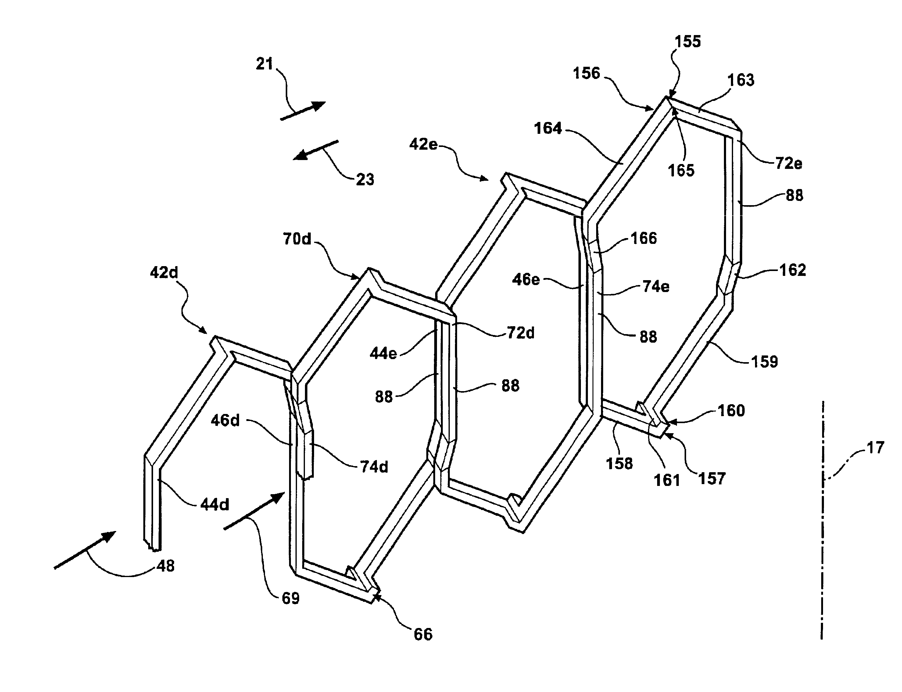
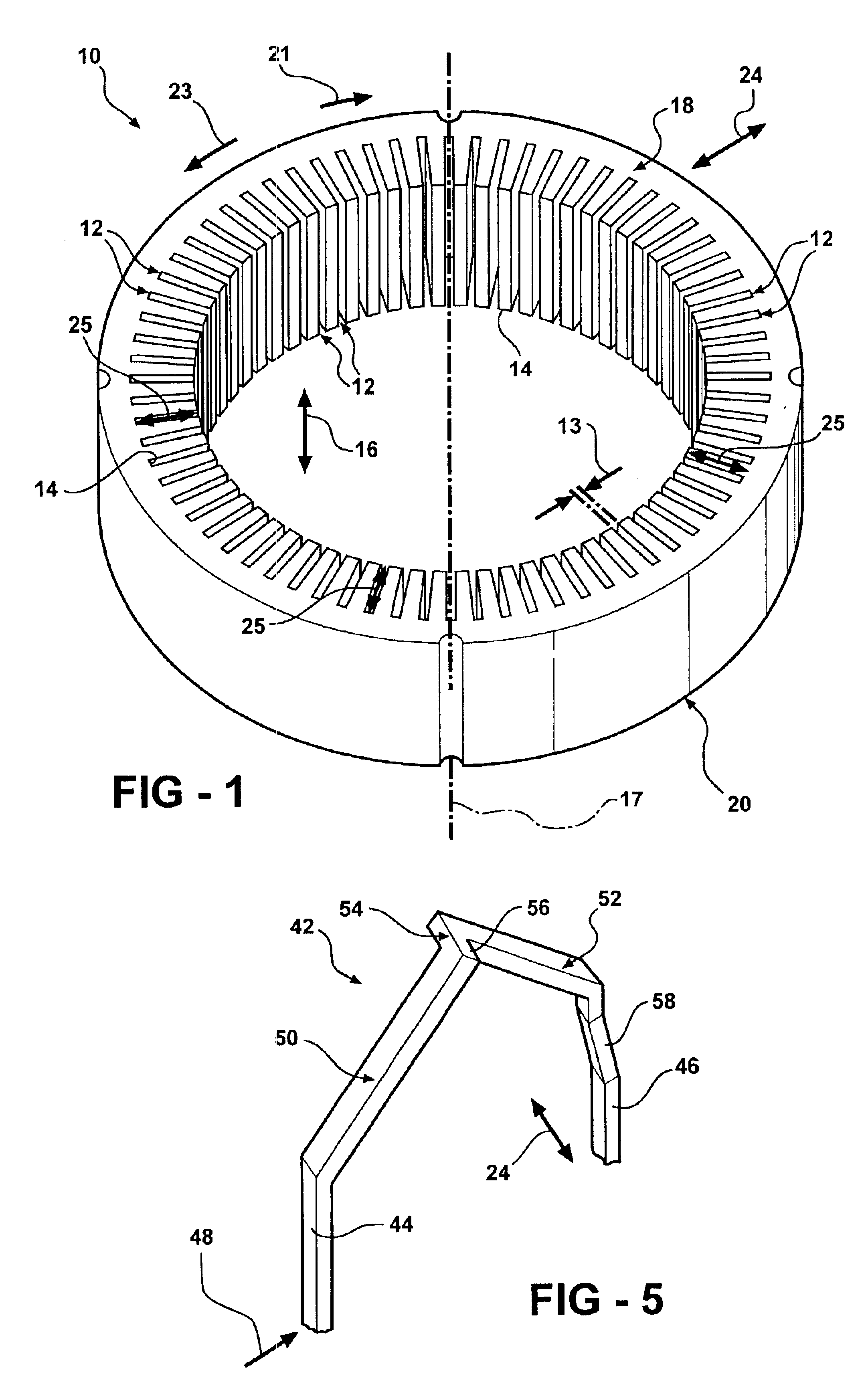
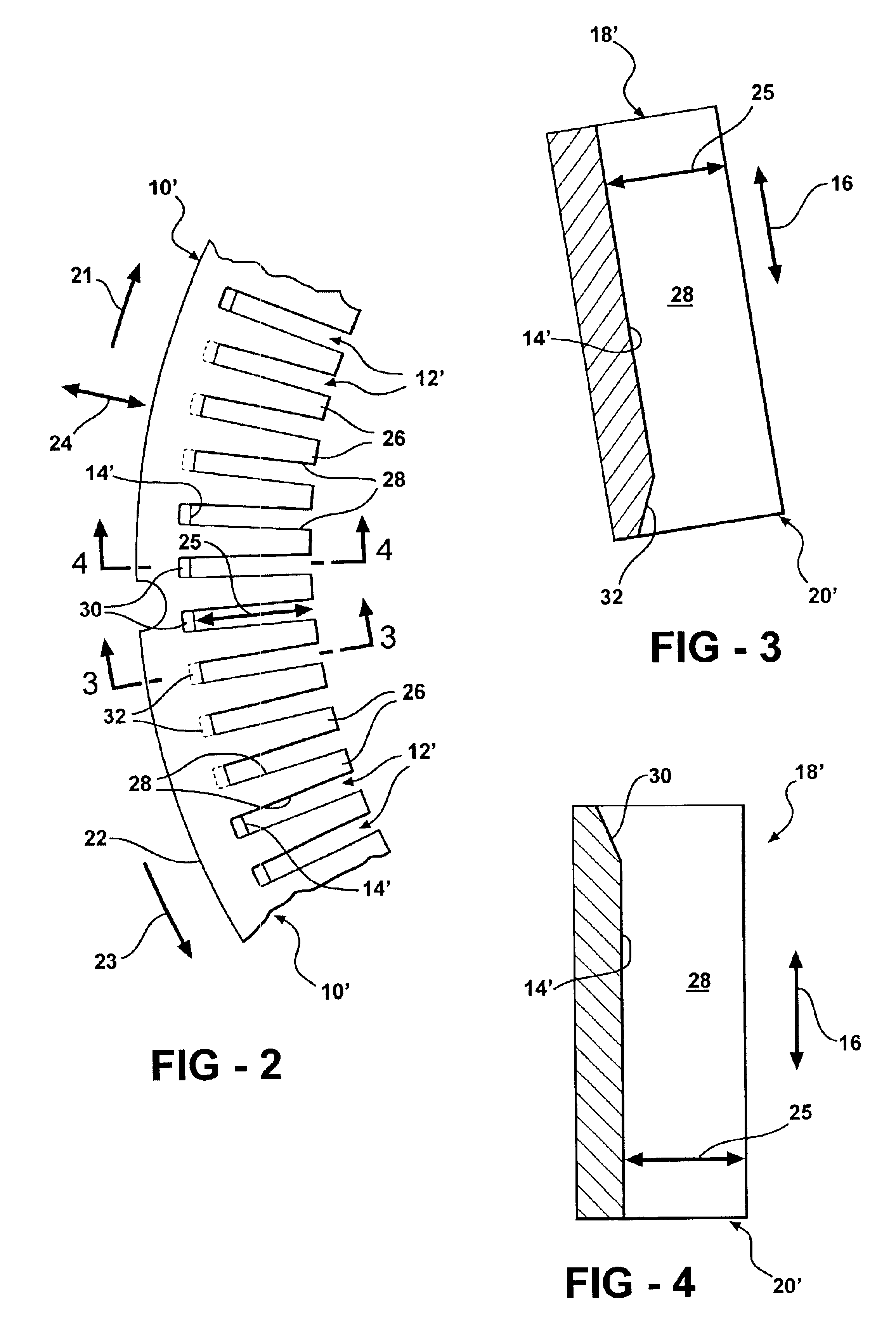
[0023]Referring now to FIG. 1, a generally cylindrically-shaped stator core is indicated generally at 10. The stator core 10 includes a plurality of core slots 12 formed in a circumferential interior surface 14 thereof. The core slots 12 extend in a direction, indicated by an arrow 16, parallel to the central axis 17 of the stator core 10 between a first end 18 and a second end 20 thereof. An axially upward direction is defined as moving toward the first end 18 of the stator core 10 and an axially downward direction is defined as moving toward the second end 20 of the stator core 10. Preferably, the core slots 12 are equally spaced around the circumferential inner surface 14 of the stator core 10 and the respective inner surfaces 14 of the core slots 12 are substantially parallel to the central axis 17. A circumferential clockwise direction is indicated by an arrow 21 and a circumferential counterclockwise direction is indicated by an arrow 23. The core slots 12 define a depth 25 al...


PUM


Abstract

An alternator stator having cascaded end loop segments includes a multi-phase stator winding that is adapted to be placed in a plurality of circumferentially spaced axially-extending core slots in a surface of a stator core. The stator winding includes a plurality of straight segments alternately connected at the first and second ends of the stator core by a plurality of end loop segments to form the winding. The end loop segments include first and second sloped portions meeting at an apex portion. Each of the end loop segments includes a radial outward adjustment and a radial inward adjustment and forms a cascaded winding pattern.

Description

CROSS-REFERENCE TO RELATED APPLICATION[0001]This application is a continuation-in-part of co-pending U.S. patent application Ser. No. 10 / 324,319 filed Dec. 19, 2002.[0002]This application claims the benefit of U.S. provisional patent application Ser. No. 60 / 454,996 filed Mar. 14, 2003.BACKGROUND OF THE INVENTION[0003]The present invention relates generally to dynamoelectric machines and, in particular, to a stator winding for a dynamoelectric machines having cascaded end loops.[0004]Dynamoelectric machines, such as alternating current electric generators, or alternators are well known. Prior art alternators typically include a stator assembly and a rotor assembly disposed in an alternator housing. The stator assembly is mounted to the housing and includes a generally cylindrically-shaped stator core having a plurality of slots formed therein. The rotor assembly includes a motor rotor attached to a generally cylindrical shaft that is rotatably mounted in the housing and is coaxial wi...

Claims


Application Information

Patent Timeline
Patent Type & Authority Patents(United States)
IPC IPC(8): H02K3/12H02K3/24H02K15/00H02K3/04H02K1/16H02K3/50H02K15/04
CPCH02K3/12H02K15/0435H02K3/24H02K15/0478
Inventor NEET, KIRK E.
Owner BORGWARNER INC
Why Eureka
Try Eureka