Alternator for vehicle
a technology for alternators and vehicles, applied in the direction of magnetic circuit rotating parts, magnetic circuit shapes/forms/construction, windings, etc., can solve the problems of high-power alternators that generate heat at an increased rate, high-power alternators with a small cooling fan tend to have the problem of temperature rise, and the alternator in japanese application 7-194060 tends to be heavy and large in siz
- Summary
- Abstract
- Description
- Claims
- Application Information
AI Technical Summary
Benefits of technology
Problems solved by technology
Method used
Image
Examples
first embodiment
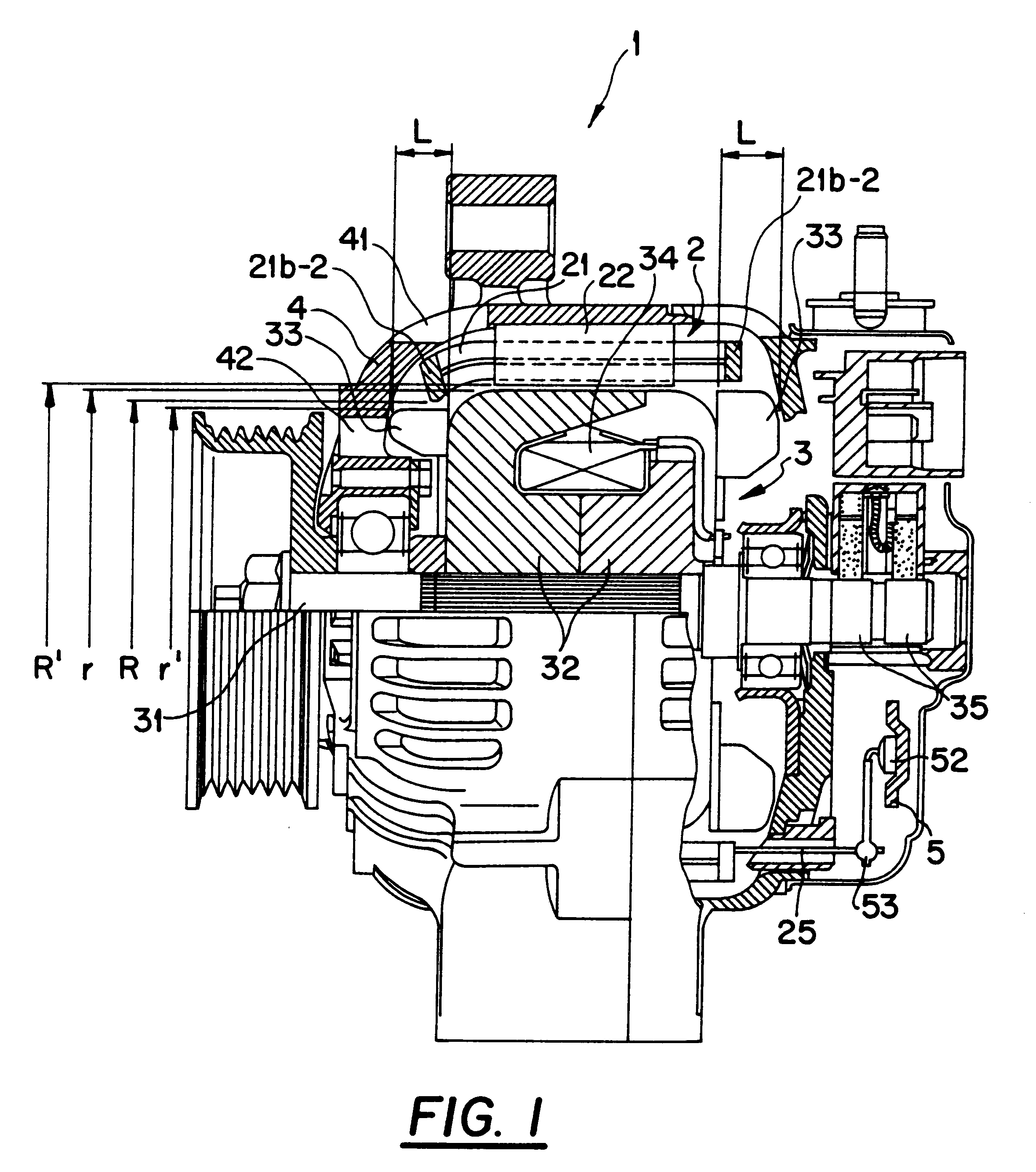
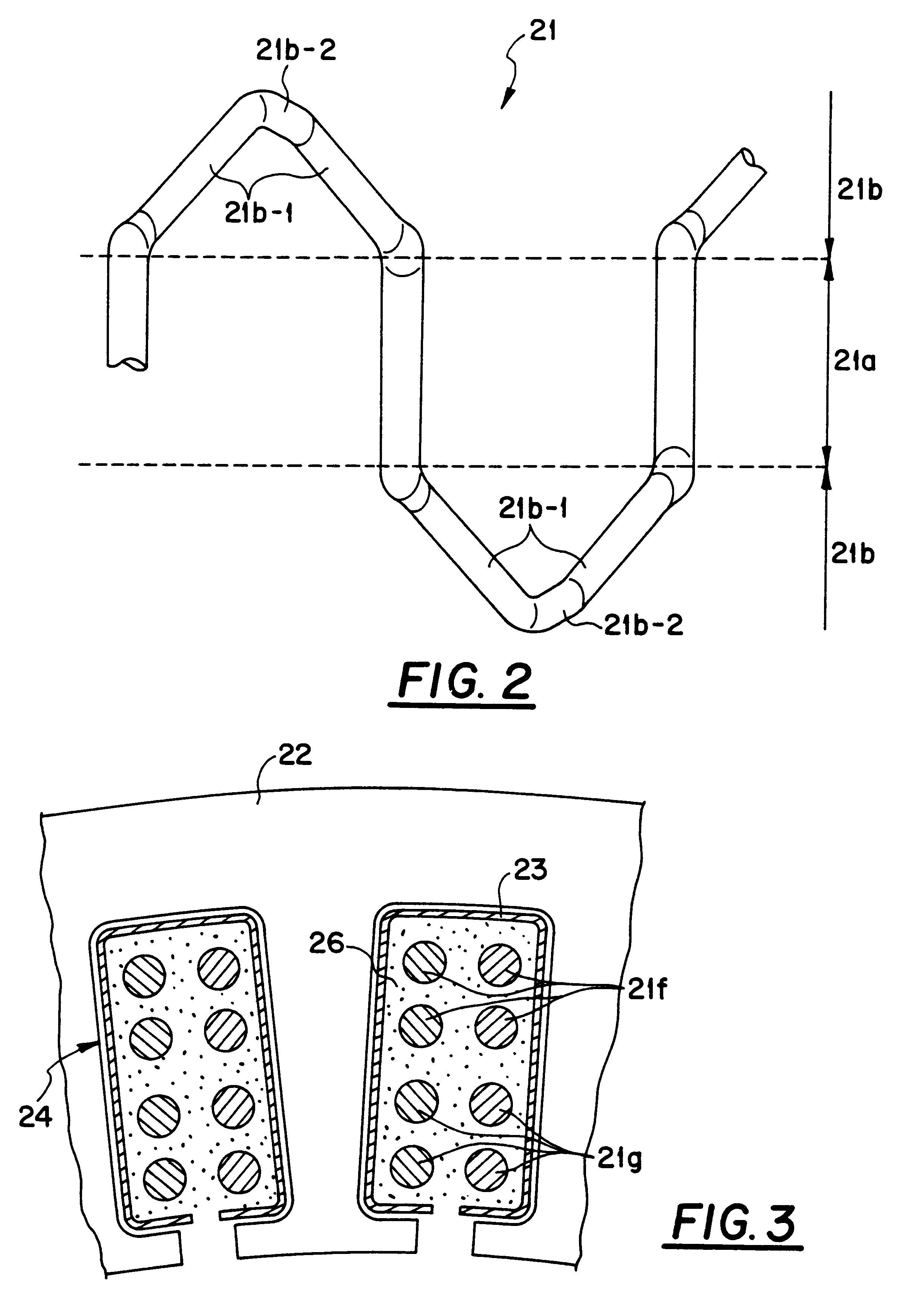
With reference to FIGS. 1 to 5, an alternator 1 for an automotive vehicle according to this invention includes a stator 2, a rotor 3, a housing 4, and a rectifier 5. The stator 2 serves as an armature. The rotor 3 generates a magnetic field. The housing 4 supports the stator 2 and the rotor 3. The housing 4 is also referred to as the frame 4. The rectifier 5 is directly connected to the stator 2. The rectifier 5 converts alternating current power into direct current power.
The rotor 3 rotates together with a shaft 31. The rotor 3 includes a pair of Lundel-type pole cores 32, cooling fans 33, a field coil 34, and slip rings 35.
The shaft 31 is connected to a pulley, being rotated and driven by an engine (not shown) mounted on the automotive vehicle for powering the same.
The housing 4 has outlets 41 for cooling winds which extend in areas opposing electric-conductor bridge portions 21b of the stator 2. The housing 41 has end faces in an axial direction which are formed with inlets 42 fo...
second embodiment
FIGS. 6 to 9 show a stator 6 in an alternator for an automotive vehicle according to a second embodiment of this invention.
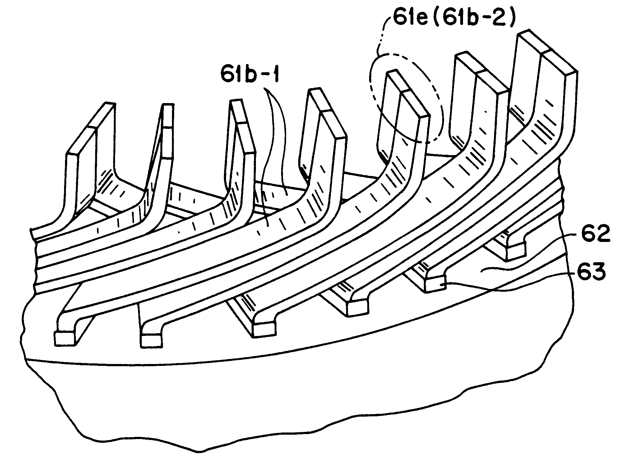
The stator 6 includes electric conductor segments 61, an iron core 62, and an insulator 63. The electric conductor segments 61 compose a winding on the iron core 62. The insulator 63 provides electric insulation between the electric conductor segments 61 and the iron core 62.
The winding is composed of the electric conductor segments 61 which are electrically connected. The winding includes turn portions 61d and connected portions 61e. The turn portions 61d are located on one side of the iron core 62 in an axial direction. The connected portions 61e are located on the other side of the iron core 62 in the axial direction.
The electric conductor segments 61 have accommodated portions 61a and bridge portions 61b. The accommodated portions 61a are placed in slots 64 in the iron core 62. The bridge portions 61b connect the accommodated portions 61a. Adjacent bridge po...
third embodiment
FIGS. 10 to 12 show a third embodiment of this invention. While two electric conductor segments are inserted into one slot in the stator in the second embodiment of this invention, four electric conductor segments are inserted into one slot in a stator in the third embodiment of this invention. The third embodiment of this invention is similar in basic structure to the second embodiment thereof.
In the third embodiment of this invention, electric conductor segments 7a and 7b approximately correspond to possible halves of the electric conductor segment 61 in FIG. 7, respectively. The electric conductor segments 7a and 7b are electrically insulated from each other as follows.
A U-shaped member is halved into electric conductor segments 7a and 7b. The electric conductor segment 7a is located outward of the electric conductor segment 7b. The outer-side electric conductor segment 7a has stepped portions similar in shape to the stepped portions in the electric conductor segment 61 of FIG. 7...
PUM
 Abstract
Description
Claims
Application Information
 - R&D
- Intellectual Property
- Life Sciences
- Materials
- Tech Scout
- Unparalleled Data Quality
- Higher Quality Content
- 60% Fewer Hallucinations
Browse by: Latest US Patents, China's latest patents, Technical Efficacy Thesaurus, Application Domain, Technology Topic, Popular Technical Reports.
© 2025 PatSnap. All rights reserved.Legal|Privacy policy|Modern Slavery Act Transparency Statement|Sitemap|About US| Contact US: help@patsnap.com


