LED light-emitting column and LED light using the same

a technology of led light and led light, which is applied in the field of led light, can solve the problems of not being widely used, the type of led light needs a bulky metal heat sink, and the cost of led light is three to six times higher than that of compact fluorescent light, and achieves good heat dissipation characteristics, high efficiency, and high output luminous flux.

Inactive Publication Date: 2015-02-05
ZHEJIANG LEDISON OPTOELECTRONICS
View PDF0 Cites 37 Cited by
  • Summary
  • Abstract
  • Description
  • Claims
  • Application Information

AI Technical Summary

Benefits of technology

[0046]The LED light-emitting column and the LED light manufactured by it provide the following advantages: good characteristic of dissipating heat, high output luminous flux, high efficiency, simple manufacturing process, and low cost. They can directly replace the incandescent lamp and the compact fluorescent light, for illumination.

Problems solved by technology

Such type of LED lights, however, needs a bulky metal heat sink.
Moreover, such type of LED lights has a higher cost that is three to six times higher than that of the compact fluorescent light with the same luminous flux as that of the LED light.
Therefore, the LED light is not widely used at present.
Although high-power LEDs packaged by means of such type of packaging technique have been mass-produced as LED elements, and the LED elements additionally provided with appropriate heat sinks have been used for illumination, such as street lamps, they still need bulky metal heat sinks.
Since LED elements are mounted on the flexible PCB or heat is dissipated by means of a shell of a driver, such LED light has a limited heat dissipation capacity and cannot be produced as an illumination lamp having a high luminous flux.
However, this cannot be easily realized in terms of process.
However, the LED chips of such LED light having LED light-emitting filaments are wrapped by both a layer of silicone and a layer of luminescent powder having a thermal conductivity of only 0.3 W / m·K, and thus it is difficult to dissipate heat of the chips.
At present, it is difficult to produce a high luminous-flux light having an output luminous flux greater than 800 Im.

Method used


Image

  • LED light-emitting column and LED light using the same
  • LED light-emitting column and LED light using the same
  • LED light-emitting column and LED light using the same

Examples


Embodiment Construction

[0059]The technical solution of the present invention will be further explained in detail, by the following embodiments, with reference to the accompanying drawing. Throughout the specification, the same or similar reference numerals will indicate the same or similar components. The explanation to the implementing of the present invention with reference to the accompanying drawing is intended to interpret the general inventive concept of the present invention, instead of limiting the present invention.

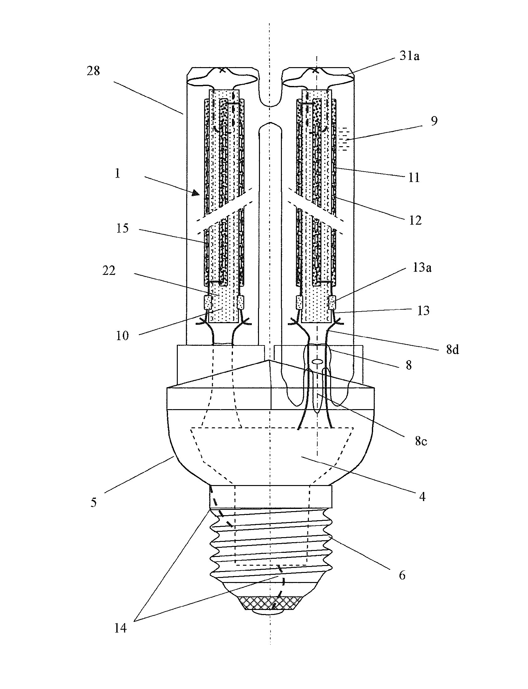
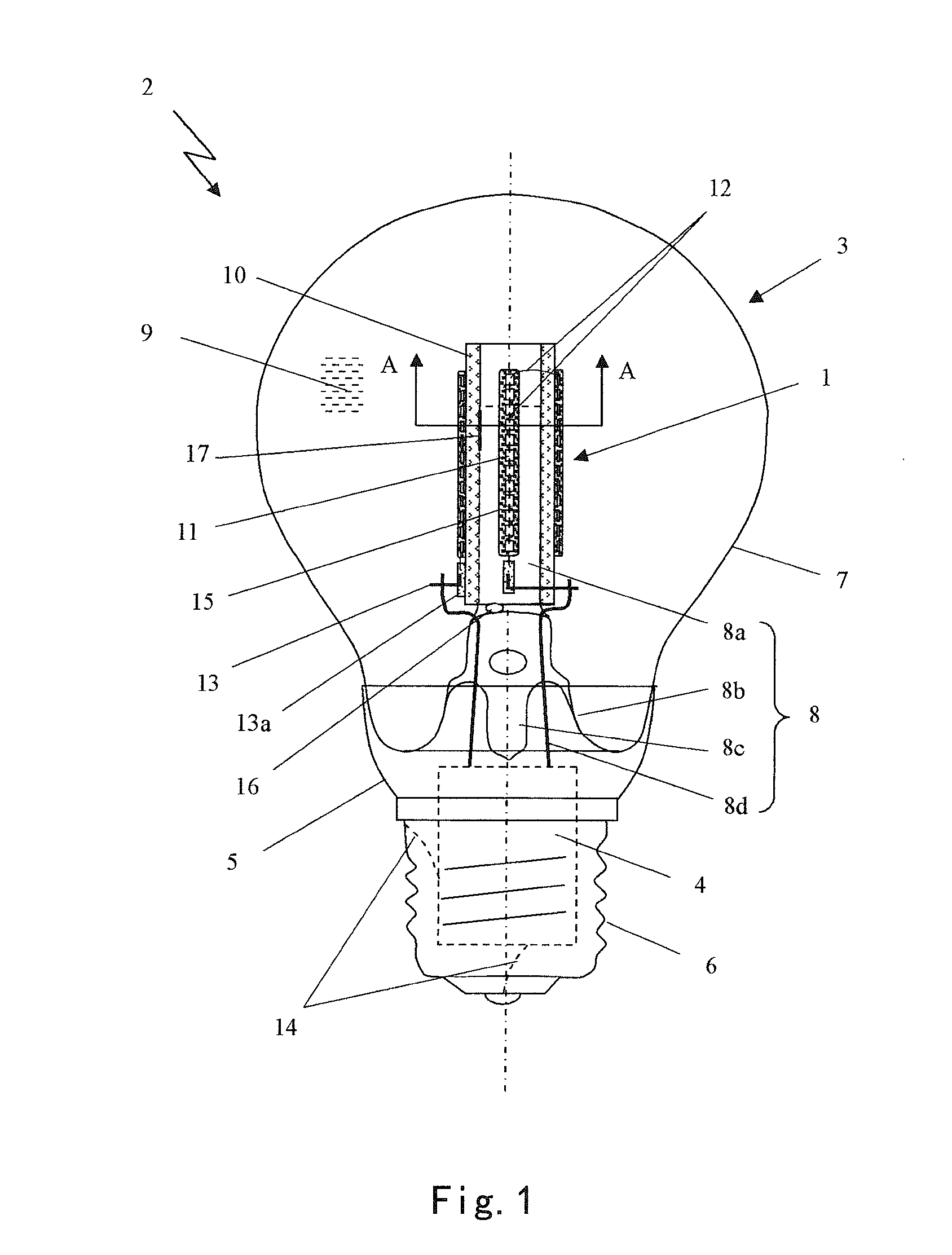
[0060]FIG. 1 is a schematic structure view of a LED light 2 provided with a LED light-emitting column 1 in accordance with an embodiment of the present invention. The LED light 2 comprises at least one LED light-emitting column 1, a light-transmitting or transparent bulb shell 3, a LED driver 4 and its shell 5, and an electrical connector 6. The shell 5 of the LED driver 4 connects the light-transmitting bulb shell 3 in which the LED light-emitting column 1 is sealed, the LED driver 4 ...


PUM

PropertyMeasurementUnit
color rendering indexaaaaaaaaaa
CRIaaaaaaaaaa

Abstract

The present invention discloses a LED light-emitting column and a LED light using the same. The LED light-emitting column comprises a high thermal conductivity tube and at least one series of LED chips disposed on an outer surface of the high thermal conductivity tube. The LED light comprises a light-transmitting bulb shell vacuum-sealed and filled with a heat dissipation and protection gas, a LED driver and an electrical connector. The LED light-emitting column is fixed within the bulb shell. Electrical lead of the LED light-emitting column is connected with an outer power supply through the driver and the electrical connector. The LED light is a single bulb shell light, a multi-tube light or a U-type light.

Description

CROSS-REFERENCE TO RELATED APPLICATION[0001]This application claims the benefit of Chinese Patent Applications No. 201210063705.9 filed on Mar. 12, 2012 and titled as “LED Light Bulb”; No. 201220184752.4 filed on Apr. 26, 2012 and titled as “LED Light Bulb Capable of Emitting 4π Light”; No. 201210211538.8 filed on Jun. 21, 2012 and titled as “LED Illumination Lamp Bulb with High Luminous Flux”; No. 201220578926.5 filed on Nov. 5, 2012 and titled as “Ceramic-Tube LED Light”; No. 201220678171.6 filed on Dec. 6, 2012 and titled as “High Efficient LED Reflection Light with LED Chip Emitting 4π Light”; No. 201210591074.8 filed on Dec. 28, 2012 and titled as “LED Energy-Saving Light with U-type Light Tube”; No. 201320016905.9 filed on Jan. 11, 2013 and titled as “LED Light Bulb Capable of Emitting Lights in All Directions”; and No. 201320089879.2 filed on Feb. 27, 2013 and titled as “LED Illumination Lamp Capable of Emitting Lights in All Directions” in the State Intellectual Property Off...

Claims


Application Information

Patent Timeline
Patent Type & Authority Applications(United States)
IPC IPC(8): F21S4/00F21V31/00F21V13/08F21V15/01F21V23/02
CPCF21S4/008F21V15/011F21Y2101/02F21V13/08F21V31/005F21V23/023F21V3/02F21V29/506F21V29/86F21V29/87F21V29/89F21K9/232F21K9/233F21Y2103/37F21Y2107/00F21Y2107/30F21Y2113/17F21Y2115/10F21V3/061F21V3/10Y02B20/40F21V17/162F21V23/002F21V29/70H05B47/11Y10S362/80
Inventor GE, SHICHAOGE, XIAOQINLIU, HUABIN
Owner ZHEJIANG LEDISON OPTOELECTRONICS
Why Eureka
Try Eureka