
Bridged network system with traffic resiliency upon link failure

a network system and bridge technology, applied in the field of computer networks, can solve the problems of slow re-convergence of rstp to a new tree, inability to fast re-converge, and inability to achieve fast re-convergence,

Active Publication Date: 2012-06-12
WSOU INVESTMENTS LLC
View PDF28 Cites 51 Cited by
  • Summary
  • Abstract
  • Description
  • Claims
  • Application Information

AI Technical Summary

Benefits of technology

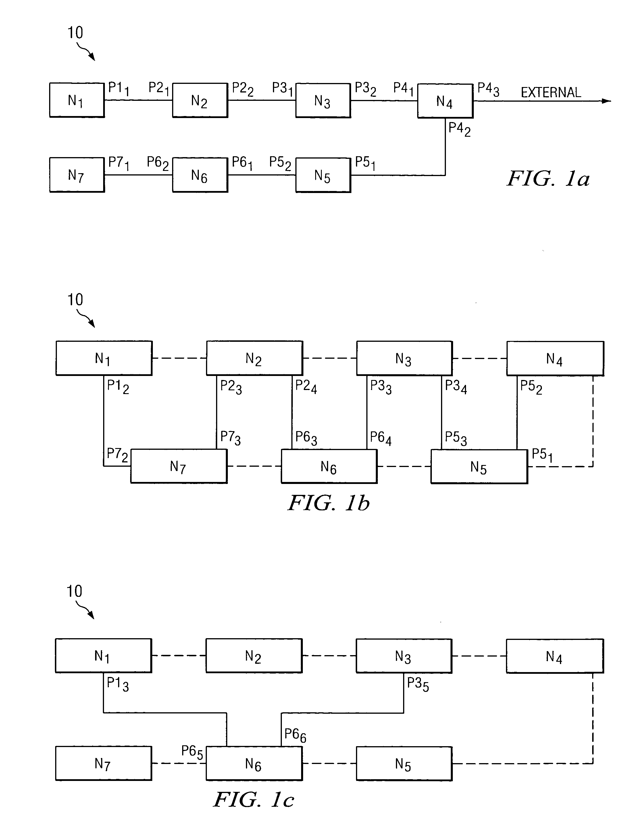
[0011]FIG. 1c illustrates the flexibility of a preferred embodiment in

Problems solved by technology

For example, the RSTP may be relatively slow to re-converge to a new tree following a failure because the protocol relies on exchange of bridge protocol data units (“BPDUs”) between the nodes and the root.
Hence, depending on the topology, fast re-convergence may not be possible and the re-convergence times can take up to two to three seconds.
Further, during operation under RSTP and in response to a failure, MAC addresses need to be flushed and re-learned which is an expensive operation.
Consequently, these approaches are not being viewed as carrier-grade technology.

Method used


Image

  • Bridged network system with traffic resiliency upon link failure
  • Bridged network system with traffic resiliency upon link failure
  • Bridged network system with traffic resiliency upon link failure

Examples


Embodiment Construction

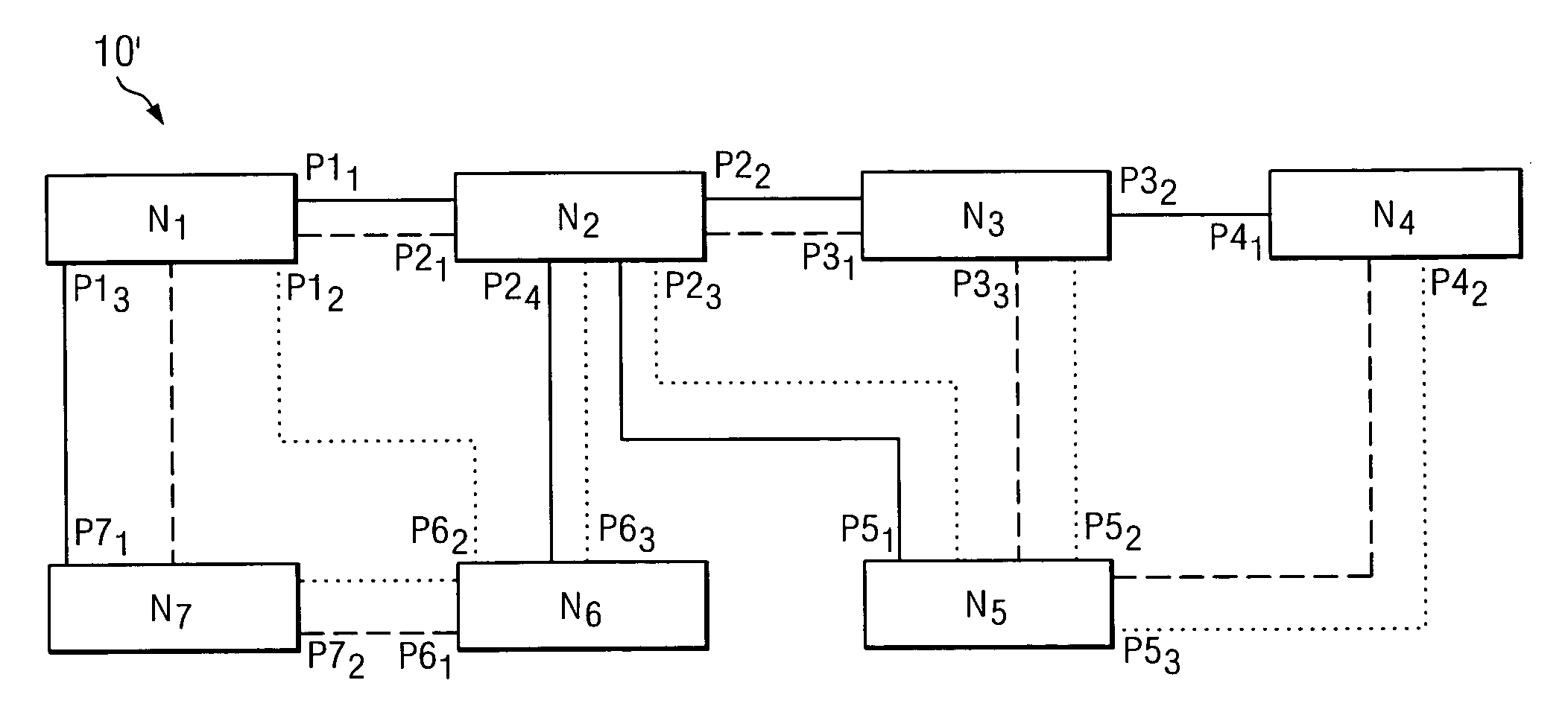
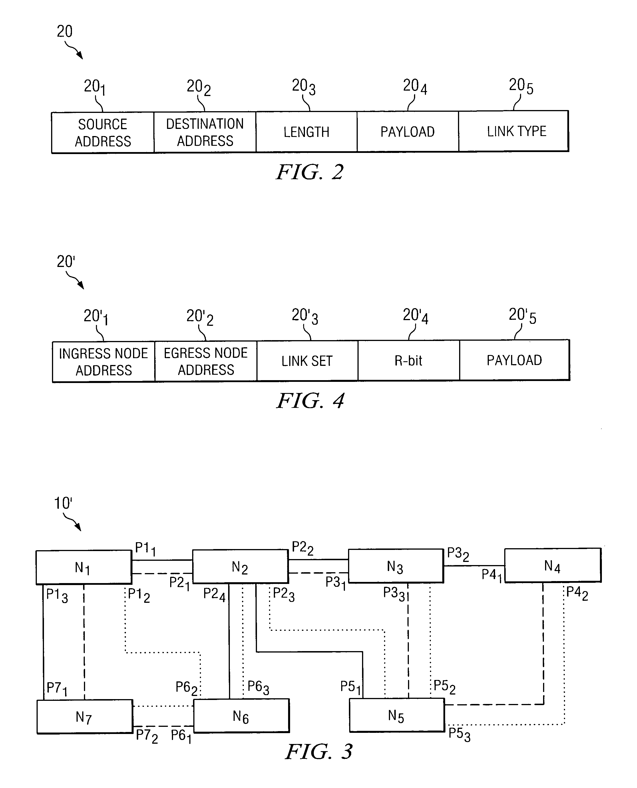
[0015]FIG. 1a illustrates a block diagram of a system 10 into which the preferred embodiments may be implemented. System 10 generally represents a bridged network such as an Ethernet network and that includes a number of network nodes N1 through N7. Such nodes are sometimes described as edge nodes or core nodes based on their location in the network. Edge nodes are so named as they provide a link to one or more nodes outside of the Ethernet network and, hence, logically they are located at the edge of the network, whereas core nodes are inside the edges defined by the logically perimeter-located edge nodes. An Ethernet network is often a publicly accessible network that provides a common domain, typically under the control of a single administrator, such as an Internet Service Provider (“ISP”). Ethernet may be used to connect to the global Internet and to connect between geographically separated sites, such as between different locations of a business entity. Also, the Ethernet netw...


PUM


Abstract

A bridged network system (10, 10′) is described comprising a plurality of nodes (N1-N7). Each node in the plurality of nodes is coupled to communicate with at least one other node in the plurality of nodes. The plurality of nodes comprise a bridge network between external nodes located externally from the plurality of nodes. Each node of the plurality of nodes is operable to perform the steps of receiving a packet (20, 20′), wherein the packet comprises a route indicator field, and responsive to the packet being received prior to a time of failure along a communication link between two of the plurality of nodes, transmitting the packet along a first route in the system to another node in the plurality of nodes. Conversely, each node of the plurality of nodes is also operable to perform the step of, responsive to the packet being received after a time of failure along a communication link between two of the plurality of nodes and in response to the route indicator field, transmitting the packet along a second route in the system to another node in the plurality of nodes, wherein the second route differs from the first route and is identified prior to the time of failure.

Description

CROSS-REFERENCES TO RELATED APPLICATIONS[0001]This application claims the benefit, under 35 U.S.C. §119(e)(1), of U.S. Provisional Application No. 60 / 419,756, filed Oct. 18, 2002, and incorporated herein by this reference.STATEMENT REGARDING FEDERALLY SPONSORED RESEARCH OR DEVELOPMENT[0002]Not Applicable.BACKGROUND OF THE INVENTION[0003]The present embodiments relate to computer networks and are more particularly directed to a bridged network system in which traffic resiliency is provided by quickly switching traffic to a pre-identified route upon a link failure.[0004]A bridged network is one type of network that has found favor in various applications in the networking industry, and for various reasons. A bridged network in many approaches is based on Ethernet switches that are Layer 2 switches, and the basic principle of operation of such a network includes learning of MAC addresses, broadcasting of unknown MAC addresses, and use of a Spanning Tree Protocol to provide loop-free op...

Claims


Application Information

Patent Timeline
IPC IPC(8): G01R31/08H04L12/28H04L12/56G06F15/173
CPCH04L45/66H04L69/40
Inventor ROUYER, JESSYCHIRUVOLU, GIRISHTANCEVSKI, LJUBISA
Owner WSOU INVESTMENTS LLC
Learn More