Sensor for a header height control system

a technology of height control system and sensor, which is applied in the field of sensors for indicating the height of the harvesting head of the combine, can solve the problems of severe damage, crushing the sensor between the header and the ground, and their ability to handle rough treatment, so as to reduce the movement of the sensor arm

Active Publication Date: 2012-06-19
DEERE & CO
View PDF24 Cites 27 Cited by
  • Summary
  • Abstract
  • Description
  • Claims
  • Application Information

AI Technical Summary

Problems solved by technology

One of the problems faced by agricultural combines is the necessity of keeping the harvesting head as close as possible to the ground in order to harvest as much of the crop as possible.
At the same time, the harvesting head (if it is a corn head) should not be permitted to dig into the ground or significant damage may result.
One problem with these sensors is their ability to handle the rough treatment they receive.
Furthermore, the header can be dropped flat against the ground, smashing the sensor between the header and the ground if no space is provided.
All of this can cause severe damage unless the sensor is made large and strong enough (or small and flexible enough) to avoid injury.
This arrangement suffers from several problems.
As a result it never returns to its original shape and no longer indicates the proper height above ground.
This lateral deflection poses a particular problem since the shaft of the arm is flexible, and therefore can be bent easily when the ball at the end of the arm is deflected left and right by the soil.
This leads to erroneous readings.
First, some headers do not have recesses for receiving sensors when the harvesting head is lowered to the ground.
The sensor arm of these patents avoids using the coil spring of the '395 patent for flexibility, but the resulting curved and flexible arm of the '299 patent is thin and easily damaged.

Method used


Image

  • Sensor for a header height control system
  • Sensor for a header height control system
  • Sensor for a header height control system

Examples


Embodiment Construction

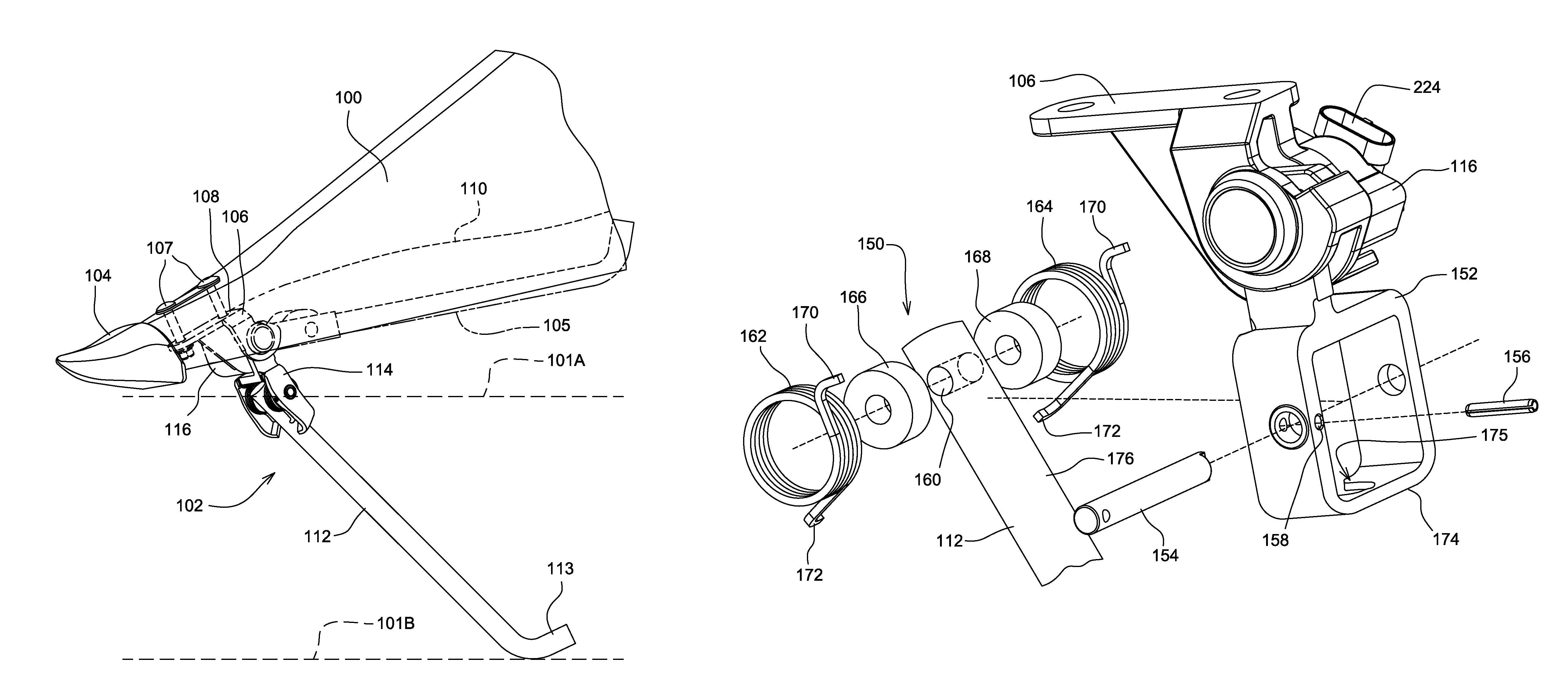
[0031]In FIG. 1, a point 100 for a row crop harvesting head (a corn head) is illustrated together with a header height sensor 102 mounted to a forward end thereof. The point 100 is typically made out of a rotomolded plastic, such as polyethylene or polypropylene.

[0032]A metal tip 104 is fixed to a forward end of the point 100 to provide a wear surface for the point 100 whenever it skids across the ground. Header height sensor 102 is fixed to point 100 immediately behind metal tip 104 by threaded fasteners 107. Header height sensor 102 includes a bracket 106 having a planar upper surface 108. This bracket 106 is fixed to a planar surface of point 100 that faces downward and is formed in a downwardly opening cavity 110 inside point 100.

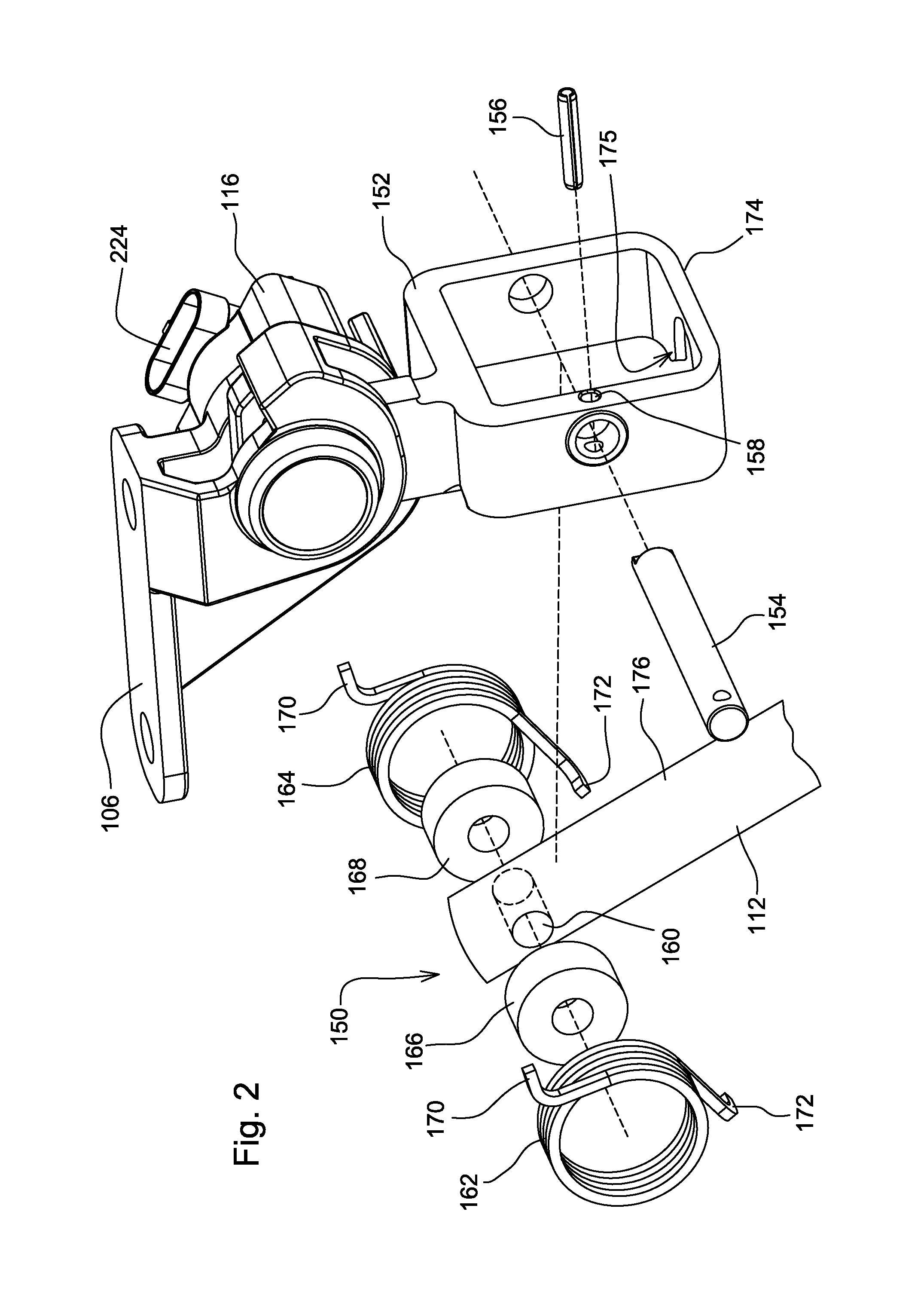
[0033]Header height sensor 102 includes an elongate sensor arm 112 that is rigid and that is coupled to a reversing joint 114, which in turn is coupled to a position sensor 116 which in turn is coupled to the bracket 106.

[0034]The sensor 102 first touch...


PUM


Abstract

A header height sensor (102) for an agricultural harvester has an elongate sensor arm (112), a reversing joint (114) and a rotary sensor (116) mounted to a bracket (106) that is fixed to a point (100) of a harvesting head. The reversing joint includes a housing (152) that limits the deflection of the sensor in a lateral direction.

Description

RELATED APPLICATIONS[0001]This application is related to and claims priority to U.S. patent application Ser. No. 12 / 776,115, filed May 7, 2010, which is incorporated herein by reference for all that it teaches.FIELD OF THE INVENTION[0002]The invention relates generally to agricultural combines. It relates in particular to header height control systems. More particularly it relates to sensors for indicating the height of a harvesting head for a combine.BACKGROUND OF THE INVENTION[0003]Agricultural combines are typically equipped with a harvesting head that is disposed at the front of the vehicle to engage crop as the vehicle travels through the field, separate it from the ground, and convey it to the threshing, separating, and cleaning systems within the combine vehicle itself.[0004]One of the problems faced by agricultural combines is the necessity of keeping the harvesting head as close as possible to the ground in order to harvest as much of the crop as possible. At the same time,...

Claims


Application Information

Patent Timeline
Patent Type & Authority Patents(United States)
IPC IPC(8): A01D41/14A01D46/08A01D75/28
CPCA01D41/141
Inventor VANDEVEN, MICHAEL L.HEIM, DANIEL M.SILVER, DENNIS P.BOMLENY, DUANE M.
Owner DEERE & CO
Why Eureka
Try Eureka