Dialysis implant and methods of use

a technology of implanted devices and dialysis, which is applied in the field of peritoneal dialysis, can solve the problems of not being able to incorporate safeguards, fail to incorporate control mechanisms required for effective dialysis without, and increase the number of painful punctures needed to introduce the dialysis solution, so as to prevent excessive bladder pressure, low or high peritoneal pressure, and increase the applied strength of magnetic forces

Active Publication Date: 2012-06-19
SEQUANA MEDICAL NV
View PDF86 Cites 35 Cited by
  • Summary
  • Abstract
  • Description
  • Claims
  • Application Information

AI Technical Summary

Benefits of technology

[0016]The peritoneal and urinary pressure sensors can be loose in the peritoneal cavity and bladder, respectively, for example by being tethered but free-floating. The peritoneal and urinary pressure sensors can be incorporated into the first and second discharge conduits, respectively. The pressure sensors can be incorporated into the peritoneourinary pump housing. The peritoneal and urinary pressure sensors control the peritoneourinary pump in order to prevent excessive bladder pressure or abnormally low or high peritoneal pressure. The implantable dialysis device can also have moisture, protein, strain (e.g., in the bladder wall), nerve sensors (e.g., to detect nerve signals in the bladder, for example, to detect fullness), or combinations thereof.
[0017]The magnetically coupled pump powering mechanism can be used to directly drive the peritoneourinary pump by the transdermally application of magnetic forces and / or to inductively recharge the internal battery. In one embodiment, for example when the peritoneourinary pump is directly driven by magnetic forces, the first discharge conduit can pass from the subcutaneous space into the peritoneal cavity. The peritoneourinary pump can reside in the subcutaneous space. The second discharge conduit can pass from the subcutaneous space into the bladder. The subcutaneous location of the peritoneourinary pump can increase the applied strength of magnetic forces used to drive the peritoneourinary pump.
[0018]In a second embodiment, for example when the internal battery is inductively recharged, the implantable peritoneourinary pump system can be located anywhere in the peritoneal, urinary or subcutaneous space. The inductive recharging coil can be located in close proximity to the skin, for example, to increase the effectiveness of battery recharging.
[0021]The reservoir can be in fluid communication with the first transfer conduit and the filling port. The reservoir can be made, in part or whole, from an impermeable material. The impermeable material can prevent or minimize undesired leakage of dialysate into the peritoneal cavity. The implanted location of the reservoir can allow for the accommodation of large volumes of concentrated solute inside the reservoir. The reservoir can be located within the peritoneal cavity.
[0024]The second conduit can be in fluid communication with the infusion pump and the peritoneal cavity. The second conduit, with one or more perforations, can function as the first conduit of the implantable peritoneourinary pump system component of the device. The second conduit can terminate in a mixing chamber. The mixing chamber can dilute the concentrated or solid dialysate with the peritoneal fluid, for example, prior to discharge into the peritoneal cavity. Diluting and / or mixing the concentrated or solid dialysate with the peritoneal fluid can prevent local reaction, for example a hyperosmotic reaction, to the mixed fluid.
[0027]A method of using the implantable dialysis device in an animal having a peritoneal cavity and a bladder is disclosed. The method can include pumping dialysate, or other osmotic or other agent, from the reservoir into the peritoneal cavity. The method can include pumping some or all of the contents of the peritoneal cavity into the urinary bladder for evacuation, for example, after a time-delay from the introduction of additional agents into the peritoneal cavity. The method can include the percutaneous refilling of the reservoir. The method can include the use of timers and pressure sensors to automatically administer peritoneal dialysis. The method can minimize conscious patient interaction, for example, only requiring conscious patient interaction for the refilling of the reservoir and the recharging or activating of the pumps.

Problems solved by technology

The system disclosed by O'Byrne, however, fails to increases the number of painful punctures needed to introduce the dialysis solution, fails to incorporate safeguards against pathologically high pressures in the urinary bladder or pathologically low levels of peritoneal fluid, fails to incorporate control mechanisms required for effective dialysis without dehydration, and fails to prevent loss of peritoneal proteins with extended use.

Method used


Image

  • Dialysis implant and methods of use
  • Dialysis implant and methods of use
  • Dialysis implant and methods of use

Examples


Embodiment Construction

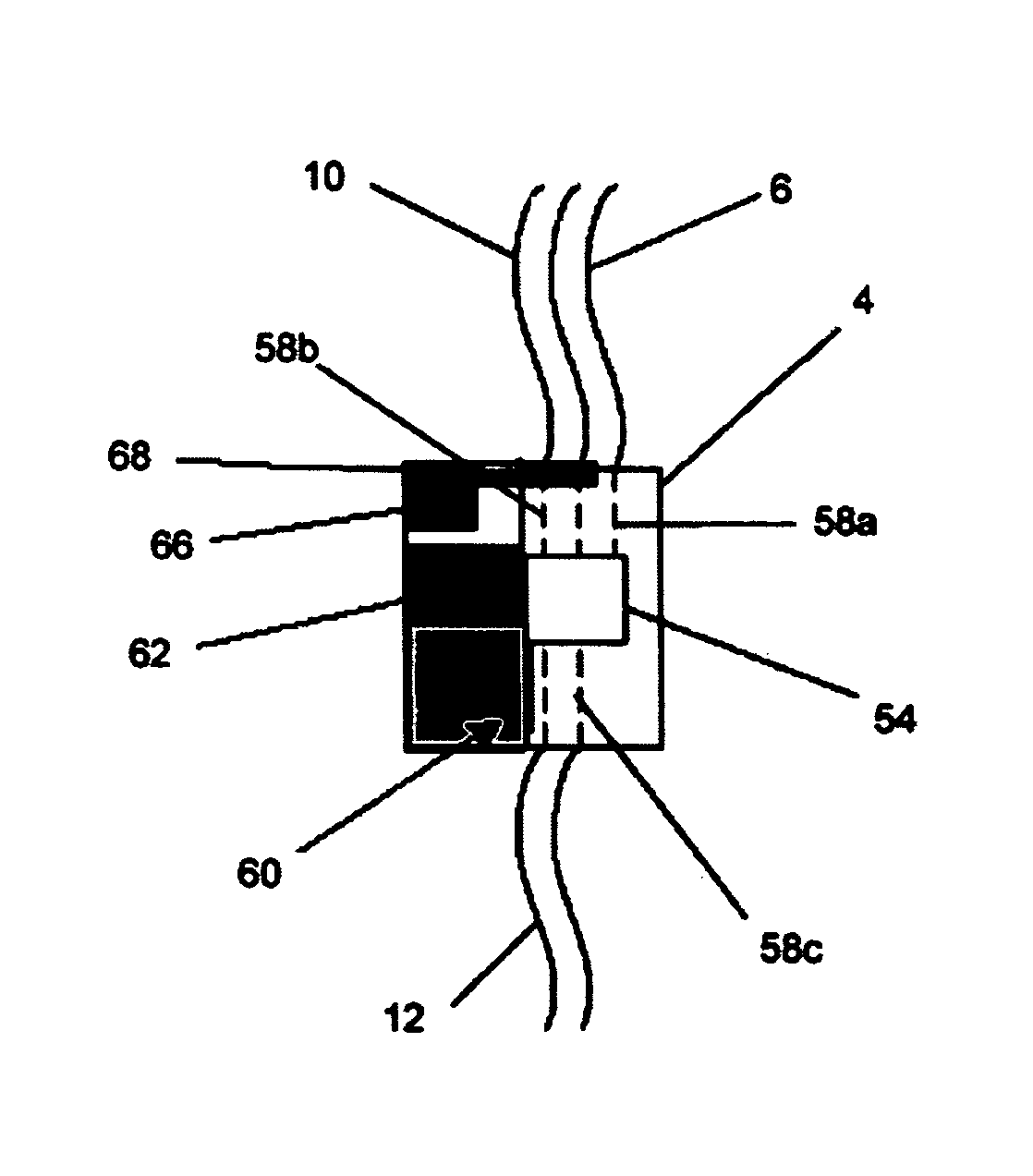
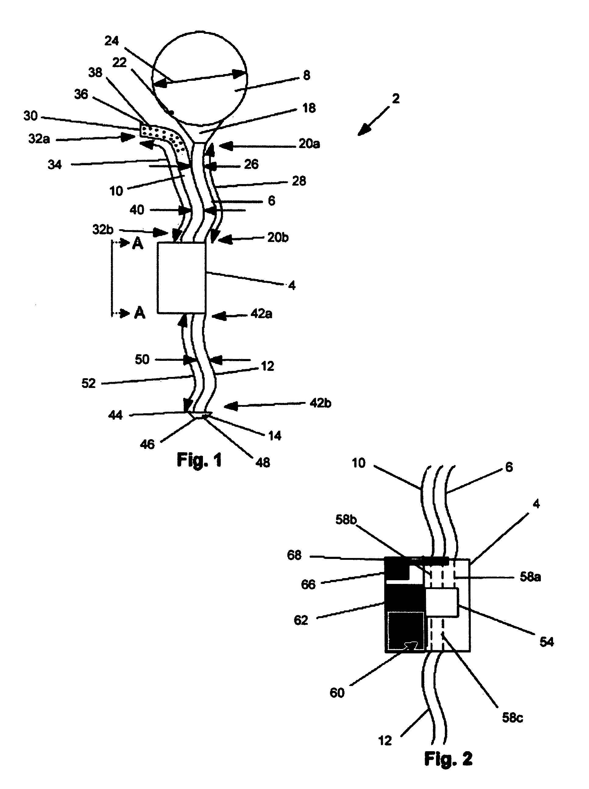
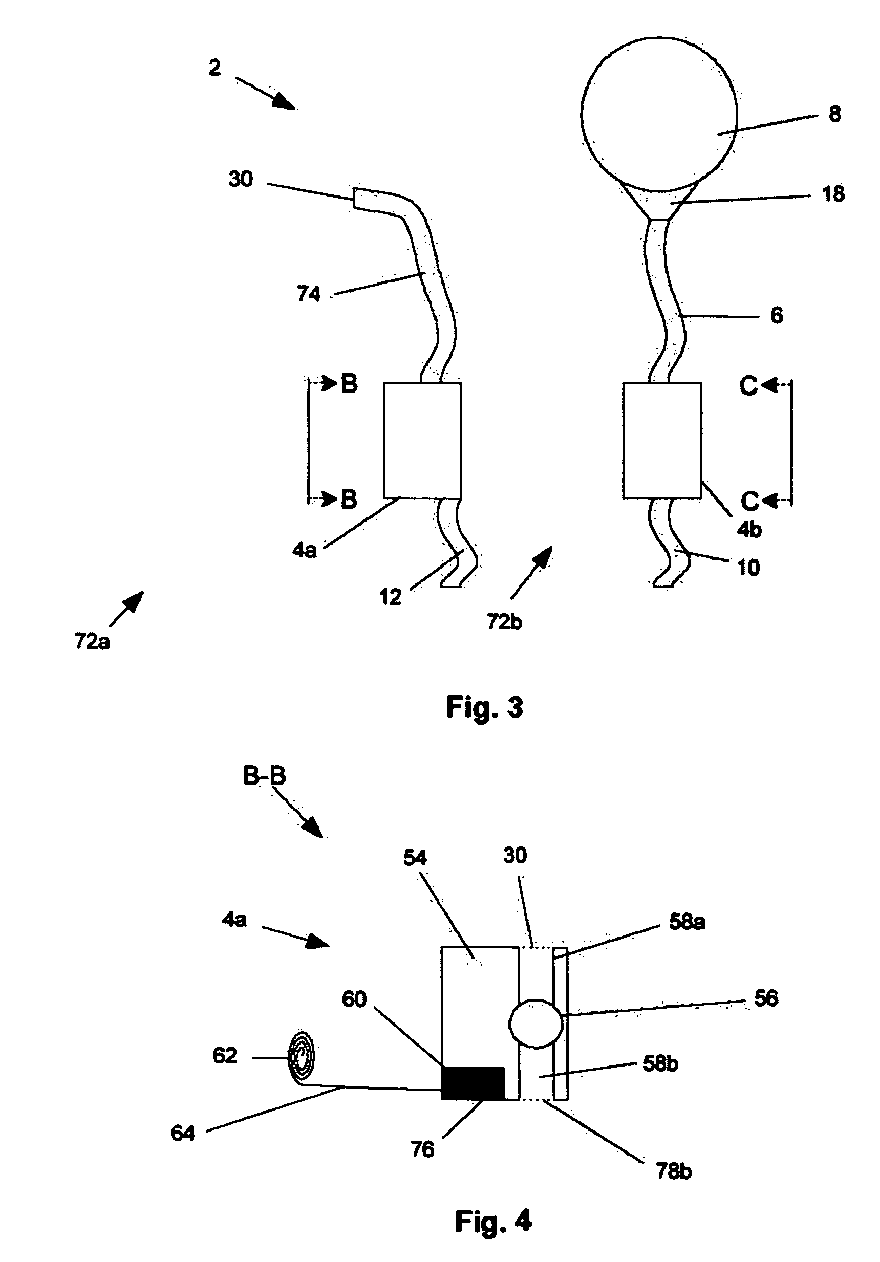
[0049]FIG. 1 illustrates an implantable dialysis device 2. The implantable dialysis device 2 can have a distributor 4. The distributor 4 can be configured to receive and distribute a dialysate and / or any other fluid or fluids, for example a solution of therapeutic and or diagnostic agents. The dialysate can be received by the distributor 4 and initially distributed through a reservoir conduit 6 to a reservoir 8. At a later time, the distributor 4 can withdraw the dialysate from the reservoir 8 and distribute the dialysate through a discharge conduit 10 to a peritoneal cavity (shown infra). At a later time, the distributor 4 can withdraw the dialysate and other waste fluids and solids from the peritoneal cavity through the discharge conduit 10. The distributor 4 can then distribute the withdrawn dialysate and waste fluids and solids through the exit conduit 12 and out an exit 14 to a bladder (shown infra).

[0050]The distributor 4 can be attached to a reservoir conduit 6. The reservoir...


PUM


Abstract

A device and methods for treating renal failure are disclosed. One embodiment of the device is an implantable peritoneal dialysis device. When in use, the device can have a semi-permeable reservoir implanted in the peritoneal cavity. The reservoir can receive blood waste and drain through one or more conduits, via a pump, to the biological bladder. Solids and / or a solution benefiting dialysis can be pumped to the reservoir and / or implanted in the peritoneal cavity.

Description

BACKGROUND OF THE INVENTION[0001]1. Field of the Invention[0002]The present invention relates to an implantable device for drug delivery and dialysis, particularly for peritoneal dialysis, and a method of using the system.[0003]2. Description of the Related Art[0004]Kidney failure is typically treated by dialysis until a kidney transplant or other treatment can replace the kidney function. Dialysis can be performed by hemodialysis or peritoneal dialysis (PD).[0005]Hemodialysis treatment removes the blood from the body, often about 0.25 L (8.5 fl. oz.) at a time, and often from a blood vessel in the arm. The extra-corporeal blood is then passed through a semi-permeable membrane that removes the waste—including excess water—otherwise filtered by healthy kidneys, from the blood without the loss of desirable molecules. Hemodialysis patients typically receive three treatment sessions per week, with each session lasting 3 to 5 hours. Because proper maintenance of hemodialysis equipment (e...

Claims


Application Information

Patent Timeline
Patent Type & Authority Patents(United States)
IPC IPC(8): A61M37/00A61K9/22A61M1/00
CPCA61M1/1678A61M1/28A61M1/1656A61M1/285A61M2205/04A61M1/1668A61M1/1676A61M2230/005
Inventor BURNETT, DANIEL R.HALL, GREGORY W.
Owner SEQUANA MEDICAL NV
Why Eureka
Try Eureka