Degassing method of ink-jet ink, production method of ink-jet ink and ink-jet printer

a production method and inkjet technology, applied in the field of inkjet printers, can solve the problems of affecting the quality of printed images, and consuming a lot of energy, and achieve excellent ink production, high viscosity pigment ink, and storage stability

Active Publication Date: 2012-06-26
KONICA MINOLTA INC
View PDF15 Cites 8 Cited by
  • Summary
  • Abstract
  • Description
  • Claims
  • Application Information

AI Technical Summary

Benefits of technology

[0036]According to the present invention, a degassing method of an ink-jet ink, a production method of the ink-jet ink, and an ink-jet printer are provided, whereby ink production, storage stability, ejection properties and graininess at printing are excellent while employing a high viscosity pigment ink.

Problems solved by technology

Of these, it is known that since the ink-jet recording system employing a piezo method repeatedly applies and reduces pressure to eject ink, minute bubbles tend to form due to cavitation, and the formed bubbles cause blank dots, or dots being out of register due to off-target ejected ink droplets during ejection of ink, to result in graininess which degrades the printed images.
However, for dispersion type ink such as a pigment ink, the method exhibited rather accelerated generation of cavitation during degassing treatment since minute bubbles were generated in the liquid during degassing, which bubbles adhered to the surface of pigment particles, while the method degasses without fail solution type inks such as a dye type ink.
However, the method is not only very time consuming and requires much energy, but also exhibits the problem for pigment type ink such that the boiling treatment exerts significant influence on storage stability of the ink after the boiling treatment, since portions of the dispersed pigment ink coagulate during such boiling.
However, with regard to degassing of a pigment ink exhibiting high viscosity of not less than 10 mPa·second at 25° C., applying high pressure to the ink was required, since a significant pressure loss during degassing arises when an ink is fed through a minute hollow fiber (namely a tube) having an inside diameter of several tens of microns.
In this case, a high pressure applied to a pigment ink before and after the degassing treatment caused mutual coagulation among pigments, to result in exerting a significant adverse influence upon storage stability of such ink.
Further, such a hollow fiber module that withstands the above-described high pressure caused problems leading to an oversized module and an increase in cost.
One possibility to decrease pressure loss during degassing might be to increase the inside diameter of the hollow fiber, but the specific surface area per volume of a module became small as the inside diameter increased, to result in a problem to have lowered production efficiency due to a significant decrease in degassing efficiency.
As described above, with regard to a pigment ink exhibiting high viscosity of not less than 10 mPa·second and not more than 50 mPa·second at 25° C., the conventional degassing methods exhibiting many problems, and specifically, large-scale production of an ink exhibited a major problem.
Further, an ink-jet printer for industrial use requires incomparably higher ejection reliability than a conventional home printer.
Under such conditions, even a small fluctuation of ejection rate of ink-jet droplets or occurrence of a nozzle which prevents ejection of ink droplets, which leads to image defects, is not acceptable.
A means to counter cavitation merely by feeding an ink degassed in advance into the ink flow channels has limits of reliability to prevent the aforesaid cavitation.
However, even in this case, a high viscosity ink having viscosity of not less than 10 mPa·second causes a significant pressure loss in a hollow fiber degassing module during degassing, so that a large solution feeding pump is required to apply high enough pressure to the ink, resulting in problems that the printer becomes oversized and the sale price rises.
With the increase in the number of nozzles, the amount of ink consumed during maintenance can no longer be ignored.
When such an ink is ejected, the above cavitation is easily generated to result in marked degraded reliability of ink ejection.
However, during head maintenance, the ink chamber within the head is required to remove all air bubbles via ink discharge through a nozzle, resulting in the problem of any ink consumed during such maintenance to be disposed of.Patent Document 1: Unexamined Japanese Patent Application Publication No.

Method used


Image

  • Degassing method of ink-jet ink, production method of ink-jet ink and ink-jet printer
  • Degassing method of ink-jet ink, production method of ink-jet ink and ink-jet printer
  • Degassing method of ink-jet ink, production method of ink-jet ink and ink-jet printer

Examples


example 1

[Preparation of Ink 1]

[0143]According to the formula of dispersion below, a pigment, a water-based solvent, and a high molecular weight dispersing agent were weighed and blended, and the total mass of the mixture was adjusted to 100 parts with deionized water. The resultant solution was initially mixed with a dissolver, and the mixed solution was subjected to dispersion via a bead mill (for example, MiniCer, produced by Ashizawa Finetech Ltd.) filled with 340 g of zirconia beads to prepare a Pigment Dispersion 1.

[0144]

C.I. Pigment Blue 15:315partsJONCRYL 61J (produced by Johnson Polymer Co.)6parts(solid contents)glycerin20parts

[0145]Subsequently, based on the formula of an ink below, each component was weighed and blended, followed by filtration of the mixture employing a #1000 mesh metal filter to prepare an Ink 1.

[0146]

Pigment Dispersion 120partsethylene glycol20partsglycerin15partstriethyleneglycolmonobutylether5partsOLFINE E1010 (produced by Nissin Chemical0.6partIndustry Co., L...

example 2

[Degassing and Evaluation of Continuous Ejection]

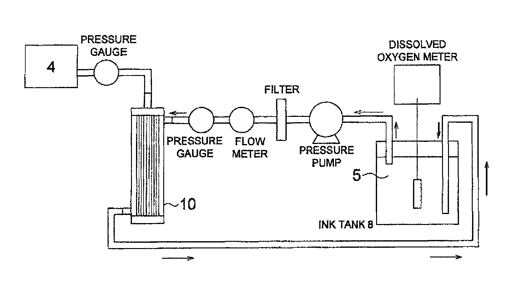
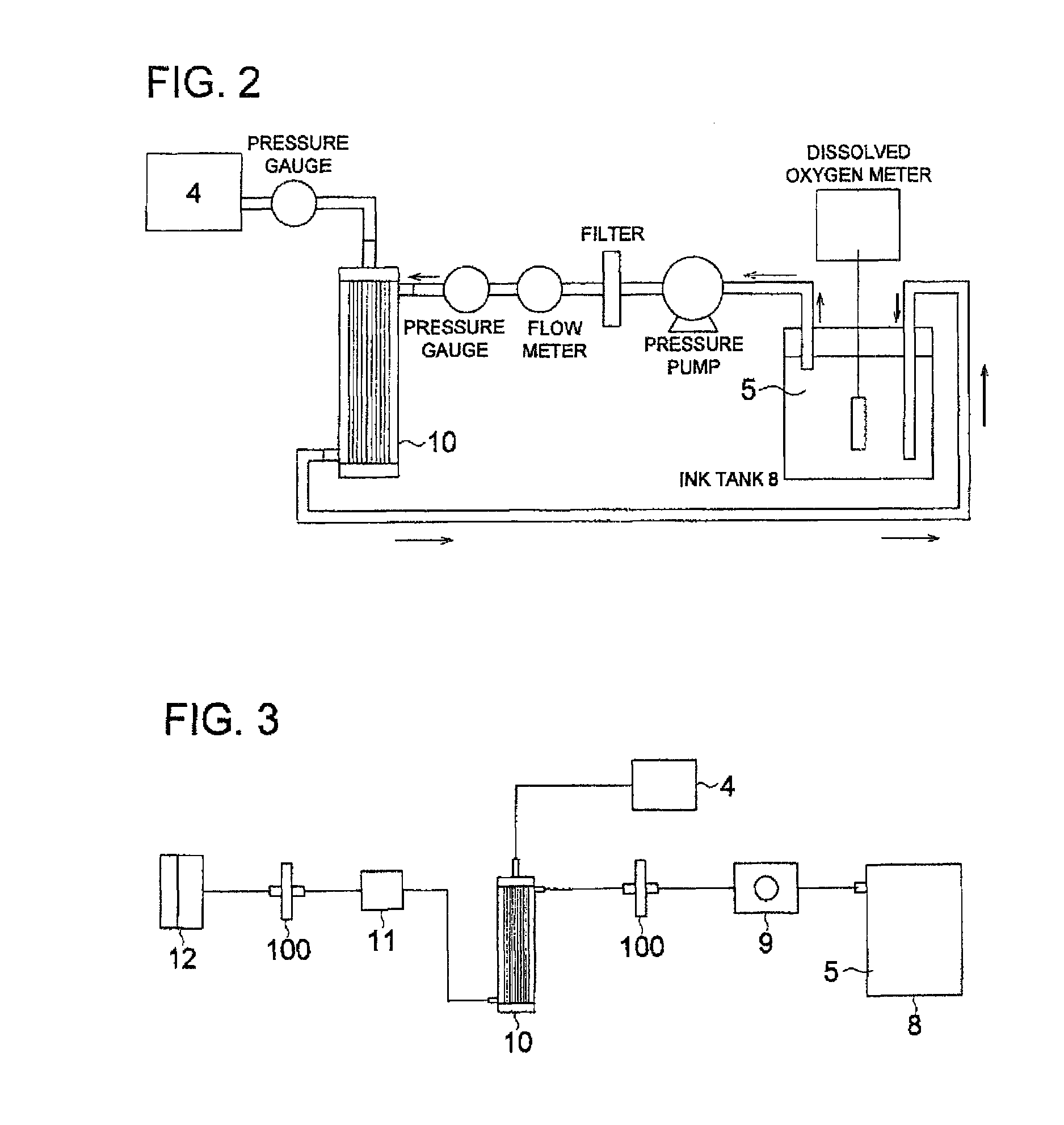
[0176]Apparatuses were arranged as illustrated in the aforesaid FIG. 3, and each Ink 1-4 was subjected to ejection from a head for one continuous hour, while being degassed employing the following hollow fiber degassing modules (A) and (B). Ink ejection properties were evaluated using the 5 evaluation levels described below. The evaluation of ink ejection was carried out by observing via a stroboscope ink droplets ejected from the nozzles. The ink flow rate was set to 24 ml / minute corresponding to the ejection. A small tube pump, WPX-1 (produced by WELCO Co., Ltd., at discharge pressure of 0.2 MPa) was employed to feed the ink, assuming that a pump is practically incorporated into a printer. Head conditions: a nozzle number of 2,000, an amount of droplet of 10 pl, and an ejection frequency of 20 kHz.

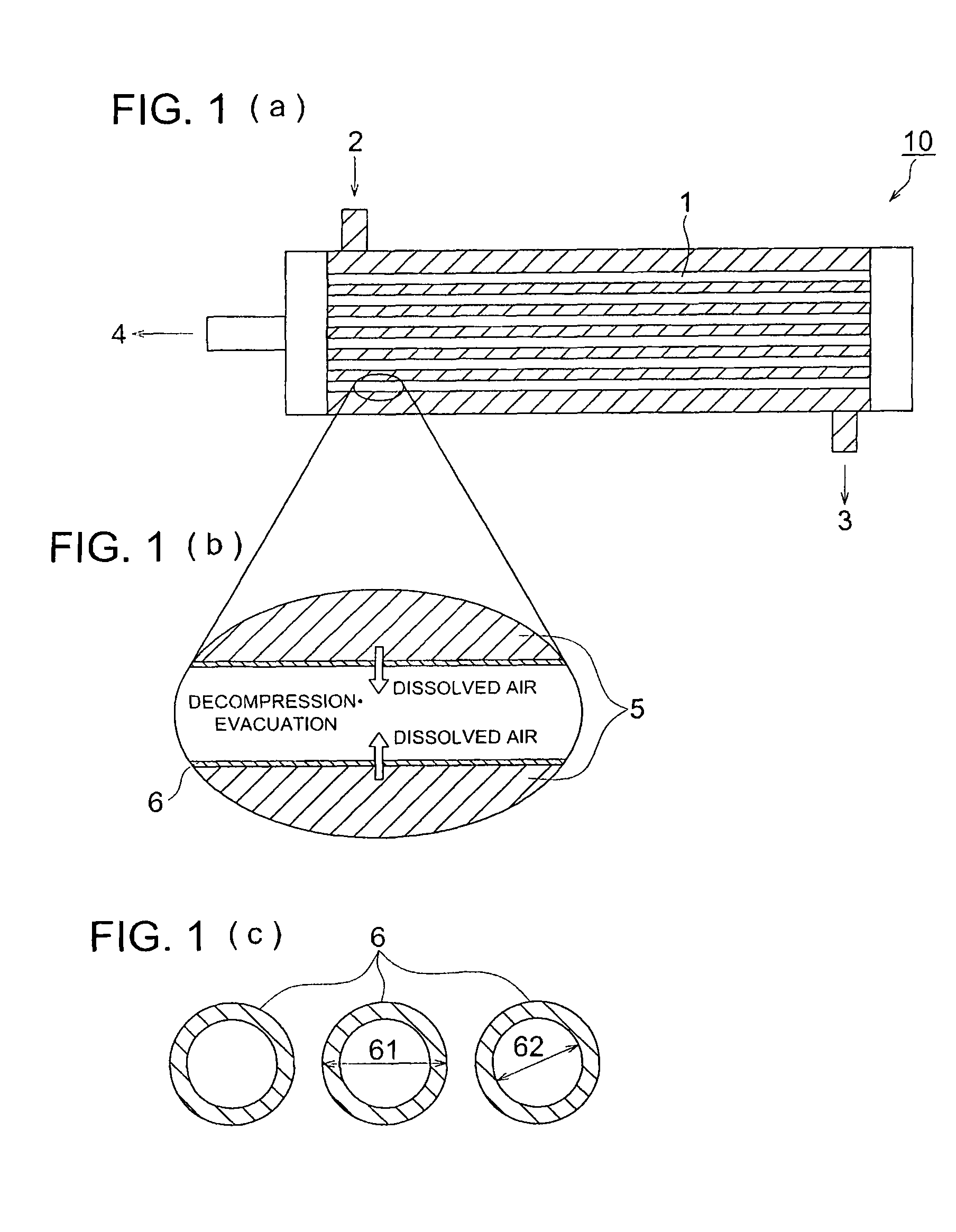
Internal Refluxing Type Hollow Fiber Degassing Module A

[0177]A small hollow fiber degassing module of an internal refluxing type having a...

example 3

[0191]Inks 7-9 were prepared in the following manner.

[Preparation of Pigment Dispersions]

[0192]According to the formula of dispersion below, a pigment, a water-based solvent, and a high molecular weight dispersing agent were weighed and blended, and the total mass of the mixture was adjusted to 100 parts with deionized water. The resultant solution was initially mixed with a dissolver, and the mixed solution was subjected to dispersion via a bead mill (for example, MiniCer, produced by Ashizawa Finetech Ltd.) filled with 340 g of zirconia beads to prepare a Pigment Dispersion 7.

Formula of Pigment Dispersion 7

[0193]

Carbon black (Mitsubishi MA100: produced15partsby Mitsubishi Chemical Co.)Disperbyk 190 (Big Chemie Corp.)6parts(solid contents)Dipropyleneglycolmonomethylether20parts

[Preparation of Ink 7]

[0194]Subsequently, according to the formula of the ink below, each component was weighed and blended, followed by filtration of the mixture employing a #1000 mesh metal filter to prepar...


PUM


Abstract

A degassing method of an ink-jet ink comprising at least a pigment, and having a viscosity of not less than 10 mPa·second and not more than 50 mPa·second at 25° C., comprising the step of: carrying out degassing employing an external refluxing type hollow fiber degassing module under a condition of a pressure loss of the hollow fiber degassing module during degassing being less than 0.1 MPa.

Description

[0001]This is a U.S. National Phase Application under 35 U.S.C. 371 of International Application PCT / JP2006 / 322946 filed on Nov. 17, 2006.[0002]This application claims the priority of Japanese Application No. 2005-345472, filed Nov. 30, 2005, Japanese Application No. 2005-345473 filed on Nov. 30, 2005 and Japanese Application No. 2006-001265 filed on Jan. 6, 2006, the entire content of each of which is hereby incorporated by reference.TECHNICAL FIELD[0003]This invention relates to a degassing method of an ink-jet ink, a production method of the ink-jet ink, and an ink-jet printer.BACKGROUND[0004]Printing of an image via an ink-jet system can be performed by a method in which ink droplets are ejected from an ink-jet recording head and adhere onto a targeted recording medium. Such ink-jet system has advantages such as a relatively simple mechanism, the low sale price, and formation of high-definition and high-quality images.[0005]Various types of ink-jet recording systems are known, a...

Claims


Application Information

Patent Timeline
Patent Type & Authority Patents(United States)
IPC IPC(8): B41J2/19
CPCB41J2/19C09D11/322
Inventor IIJIMA, HIROTAKA
Owner KONICA MINOLTA INC
Why Eureka
Try Eureka