Method of displaying a low dynamic range image in a high dynamic range

a high-dynamic range, low-dynamic range technology, applied in the direction of static indicating devices, instruments, cathode-ray tube indicators, etc., can solve the problems of loss of contrast and detail of images, linear stretch does not consider image characteristic and human visual system properties, and can only display images with a dynamic range of around 2 orders of magnitude. , to achieve the effect of increasing the dynamic range of images

Active Publication Date: 2012-06-26
HONG KONG APPLIED SCI & TECH RES INST
View PDF49 Cites 12 Cited by
  • Summary
  • Abstract
  • Description
  • Claims
  • Application Information

AI Technical Summary

Benefits of technology

[0019]There is also disclosed herein a method of increasing the dynamic range of an image comprising receiving an image comprising a plurality of pixels each having a luminance value within a first luminance dynamic range, transforming the image into red, green and blue sub-images, performing the method of claim 1 on each of the sub-images and combining the converted red, green and blue sub-images into a high dynamic range image.
[0039]There is also disclosed herein a method of increasing the luminance dynamic range of a digital image to improve viewable contest and detail in the image, the method comprising:

Problems solved by technology

However, most display devices can only display images with a dynamic range of around 2 orders of magnitude.
This results in a lose of contrast and detail of the image.
However, such linear stretch does not consider the image characteristic and human visual system property.
As a result, it can not improve the image quality.
Moreover, the linear scaling up approach may cause artifacts, such as introducing countering effect into gradually changing regions.

Method used


Image

  • Method of displaying a low dynamic range image in a high dynamic range
  • Method of displaying a low dynamic range image in a high dynamic range
  • Method of displaying a low dynamic range image in a high dynamic range

Examples


Embodiment Construction

[0056]Reference will now be made in detail to exemplary embodiments of the present invention, examples of which are illustrated in the accompanying drawings, wherein like reference numerals refer to like elements throughout.

[0057]Specifically, the present invention relates to a method of increasing the dynamic range of an image and a method of displaying a low dynamic range image in a high dynamic range. However, the invention will be described as embodied in a display device that has a high luminance dynamic range.

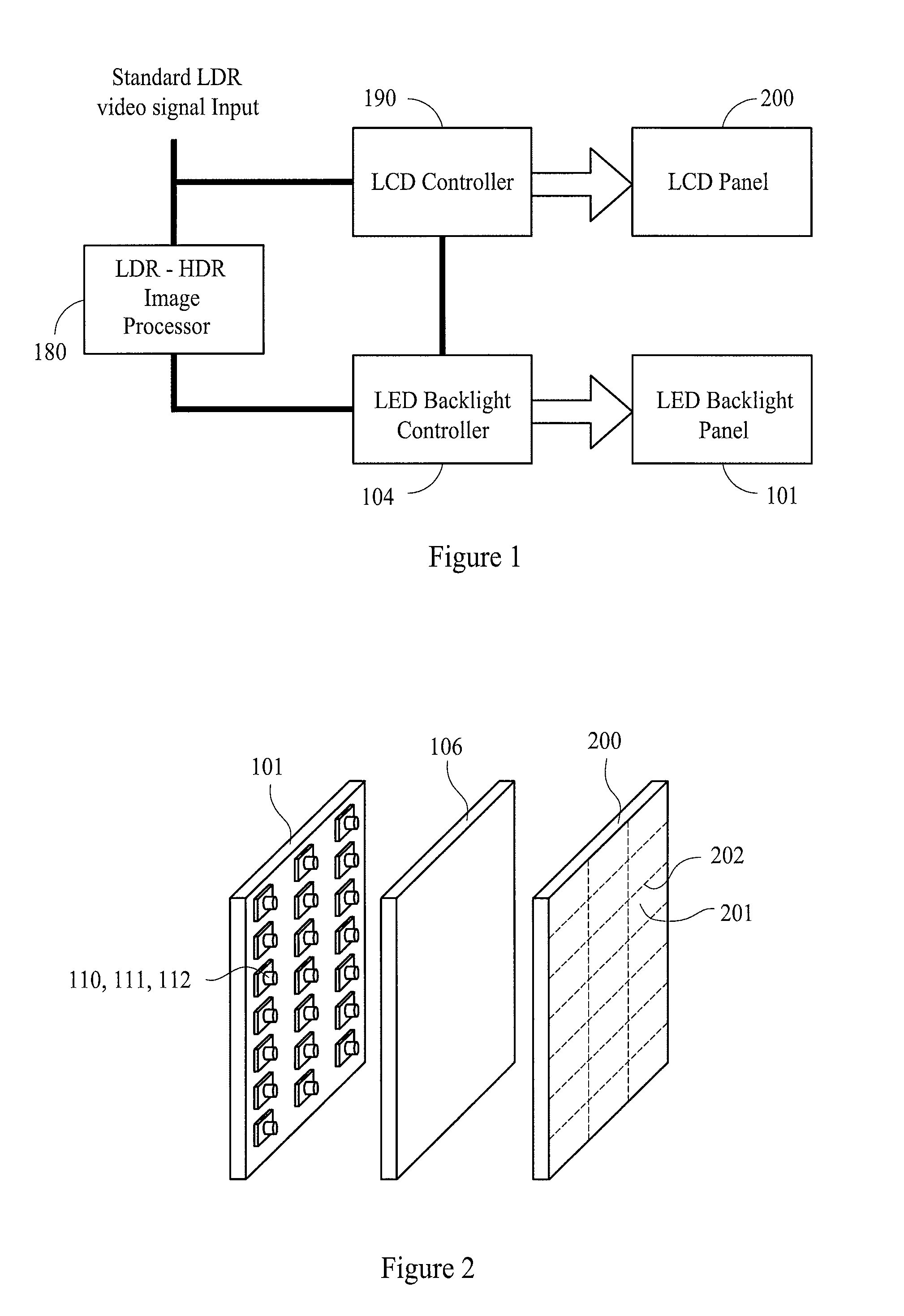
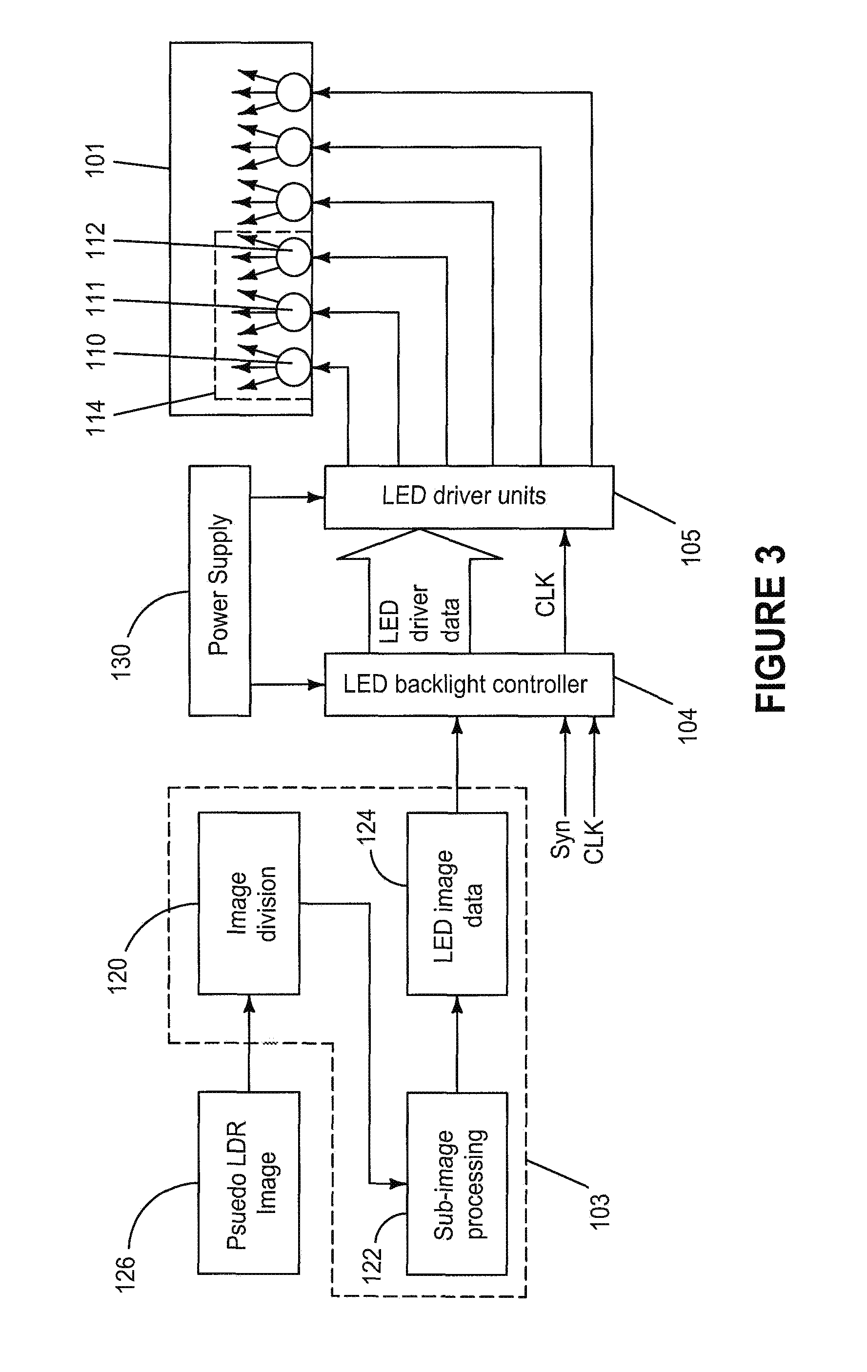
[0058]The inventors have already proposed in an earlier application Ser. No. 11 / 707,517 filed on 16 Feb. 2007 a liquid crystal display device having a dynamic backlight that can improve the contrast and luminance dynamic range of the display output. The contents of said application Ser. No. 11 / 707,517 filed on 16 Feb. 2007 are incorporated herein by reference. In a preferred embodiment of the current invention this liquid crystal display device includes an image luminance...


PUM


Abstract

A method of increasing the dynamic range of an image comprising a plurality of pixels each having a luminance value within a first luminance dynamic range. The method includes determining a background luminance value for each pixel of the image and determining a minimum and a maximum of the background luminance values. A conversion factor is then determined for each pixel of the image based on the minimum and maximum of the background luminance values. The image id converted from the first luminance dynamic range to a second luminance dynamic range by multiplying the luminance value of each pixel of the image by its conversion factor.

Description

FIELD OF THE INVENTION[0001]The present invention relates to a method of displaying an image, and in particular to displaying a low dynamic range image in a high dynamic range. The invention also relates to a method of increasing the dynamic range of an image.BACKGROUND[0002]The dynamic range of illumination in the real world which can reach up to 14 orders of magnitude from star light to sun light. The human eye can see a wide dynamic range of up to 5 orders of magnitude. However, most display devices can only display images with a dynamic range of around 2 orders of magnitude. Liquid crystal display panels for example can typically only display images having an 8-bit (256 step) luminance dynamic range. Therefore, a luminance mapping transfer is used to map from the dynamic range of the real world to the lower dynamic range of the display. This results in a lose of contrast and detail of the image. Generally this mapping is performed in the image capture stage since some digital ca...

Claims


Application Information

Patent Timeline
Patent Type & Authority Patents(United States)
IPC IPC(8): G09G3/36G09G5/02
CPCG09G3/3426G09G3/3611G09G2320/064G09G2320/0646G09G2320/066G09G2340/0428
Inventor ZHANG, WEIPENG, HUAJUNTSAI, CHEN-JUNG
Owner HONG KONG APPLIED SCI & TECH RES INST
Why Eureka
Try Eureka