High dynamic range sensor with blooming drain

a high-dynamic range, image sensor technology, applied in the direction of instruments, television systems, color signal processing circuits, etc., can solve the problems of image degradation, reduced resolution, and each has significant drawbacks, so as to improve sensitivity and extend the dynamic range of image sensors

Active Publication Date: 2010-11-02
OMNIVISION TECH INC
View PDF10 Cites 11 Cited by
  • Summary
  • Abstract
  • Description
  • Claims
  • Application Information

AI Technical Summary

Benefits of technology

[0015]An image sensor has an array of unit pixels, where each unit pixel has at least two photodiodes. The array is configured to permit independent control of the exposure times of the photodiodes within each unit pixel. A timing controller operates each unit pixel such that there is a long exposure time photodiode and a short exposure time photodiode. The timing controller's operation permits the dynamic range of the image sensor to be extended. In one embodiment the readout timing is further chosen so that short exposure time photodiodes act as overflow drains for excess charge overflowing from neighboring long exposure time photodiodes. The arrangement of long exposure time photodiodes and short exposure time photodiodes may be further alternated in the unit pixels so that a long exposure time photodiode has short exposure time photodiodes as nearest neighbors in both the vertical and horizontal dimensions. In one embodiment a microlens array preferentially focuses light into the long exposure time photodiodes to improve sensitivity.

Problems solved by technology

Many high dynamic range sensors have been proposed but each has significant drawbacks.
Some of the drawbacks of previous HDR sensors include an image degradation due to fixed pattern noise, large random noise, and a reduced resolution associated with blooming.
However, a photodiode can accumulate only a certain amount of charge during an exposure time period, which limits dynamic range.
These distributions in breakpoint cause fixed pattern noise in the image that degrades the image quality.
As a result, the image quality is not good for low light level scenes.
Other HDR image sensor approaches that have been proposed also have drawbacks.
However, one drawback of this approach is that the number of available pixels for low light level and high light level scenes is half the number of pixels in the array.
This results in a degradation of the resolution if all pixels are used to create an image.
But, this sensor has two major weak points.

Method used


Image

  • High dynamic range sensor with blooming drain
  • High dynamic range sensor with blooming drain
  • High dynamic range sensor with blooming drain

Examples


Embodiment Construction

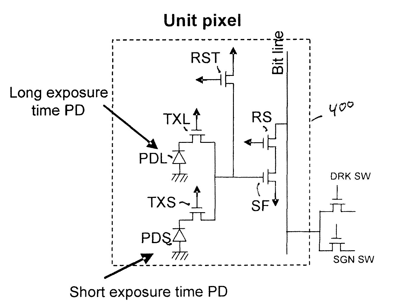
[0025]FIG. 2 is a high level block diagram of the an image sensing system 200 in accordance with one embodiment of the present invention. The image sensing system 200 includes a pixel array 205 along with a row driver 245, row decoder 255, column driver 260, column decoder 270, sample / hold block 261, amplifier 262, analog-to-DC block 275, and image processor 280. A timing and control block 250 generate signals for driving the decoders and the row driver. Separate timing signals are generated by the timing and control block 250 to operate one set of photodiodes with a long exposure time and another set of photodiodes with a short exposure time. The outputs from the long exposure time photodiodes and the short exposure time photodiodes are combined by image processor 280 to achieve a high dynamic range. Image processor 280 may, for example, be implemented as a digital signal processor.

[0026]In one embodiment each unit pixel within the pixel array 205 includes at least two photodiodes,...


PUM


Abstract

An image sensor has at least two photodiodes in each unit pixel. A high dynamic range is achieved by selecting different exposure times for the photodiodes. Additionally, blooming is reduced. The readout timing cycle is chosen so that the short exposure time photodiodes act as drains for excess charge overflowing from the long exposure time photodiodes. To improve draining of excess charge, the arrangement of photodiodes may be further selected so that long exposure time photodiodes are neighbored along vertical and horizontal directions by short exposure time photodiodes. A micro-lens array may also be provided in which light is preferentially coupled to the long exposure time photodiodes to improve sensitivity.

Description

CROSS REFERENCE TO RELATED APPLICATIONS[0001]The present application claims the benefit of and priority to U.S. Provisional Application No. 60 / 947,347, filed on Jun. 29, 2007.FIELD OF THE INVENTION[0002]The present invention is generally related to high dynamic range image sensors. More particularly the present invention is directed to inhibiting blooming in a high dynamic range image sensor.BACKGROUND OF THE INVENTION[0003]High dynamic range (HDR) image sensors are required for many applications. Many current generation image sensors, including CCD and CMOS image sensors, have about 70 dB dynamic range. However, to match the capabilities of the human eye requires a dynamic range of up to about 100 dB. For example, an image sensor for automobile applications requires more than 100 dB dynamic range to deal with different driving conditions, such as driving through a dark tunnel into bright sunshine. Additionally, some digital still camera (DSC) sensors may need more than 90 dB dynami...

Claims


Application Information

Patent Timeline
Patent Type & Authority Patents(United States)
IPC IPC(8): H04N5/335G02B3/00H04N5/355H04N5/359H04N5/369
CPCH04N5/2355H04N5/3535H04N5/35554H04N5/3592H04N5/37457H04N23/741H04N25/533H04N25/583H04N25/622H04N25/778
Inventor MANABE, SOHEISHAH, ASHISHSALADI, SASIDHARQIAN, WILLIAMNOZAKI, HIDETOSHISATYADEV, NAGARAJATAI, HSIN-CHIH DYSONRHODES, HOWARD M.
Owner OMNIVISION TECH INC
Why Eureka
Try Eureka