RF shielded enclosure for automated testing

a shielded enclosure and automated testing technology, applied in the direction of shielding efficiency measurement, electrical apparatus construction details, instruments, etc., can solve the problems of affecting any of the activities of the building, consuming a lot of time to build and build, and deteriorating the effectiveness of the room

Inactive Publication Date: 2012-06-26
QUALCOMM INC
View PDF3 Cites 4 Cited by
  • Summary
  • Abstract
  • Description
  • Claims
  • Application Information

AI Technical Summary

Problems solved by technology

The RF energy generated, if not shielded, emanates throughout the manufacturing building potentially causing interference to any of the activities in the building.
RF energy from outside the manufacturing facility may also penetrate into the building and cause interference.
They take a lot of time to build and consume valuable floor space.
Over time the rooms deteriorate in their effectiveness and require costly and time consuming replacement.
This close proximity location further increases the cost of using screen rooms because not just valuable floor space is consumed but extremely valuable manufacturing floor space close to the production lines is consumed.

Method used


Image

  • RF shielded enclosure for automated testing
  • RF shielded enclosure for automated testing
  • RF shielded enclosure for automated testing

Examples


Embodiment Construction

[0019]The description and accompanying drawings are for purposes of illustration and are not to be used to construe the disclosure in a restrictive manner. In the following description, specific details are set forth in order to provide a thorough understanding of the invention. However, it will be apparent to one of skill in the art that the invention can be practiced without these special details.

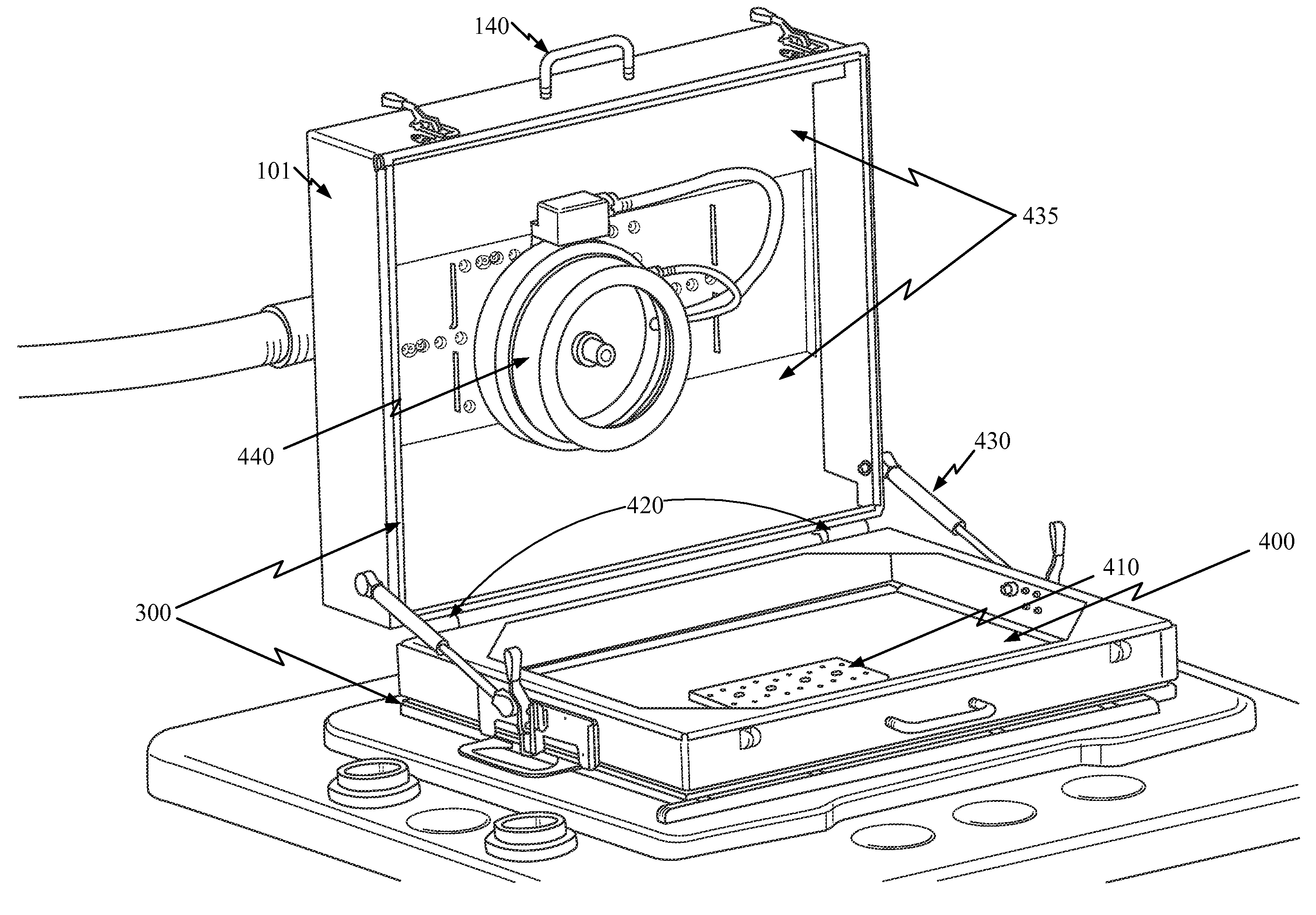
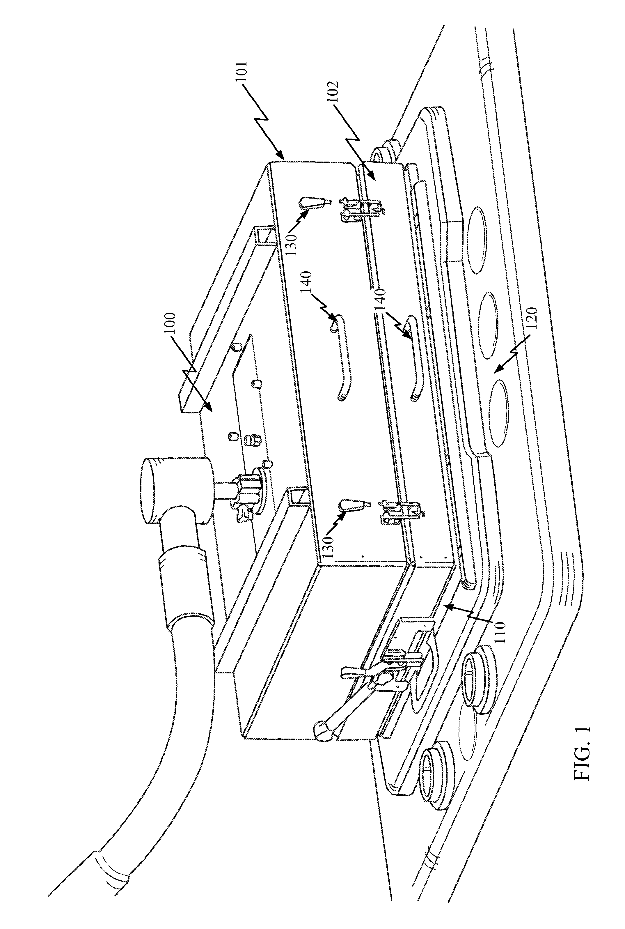
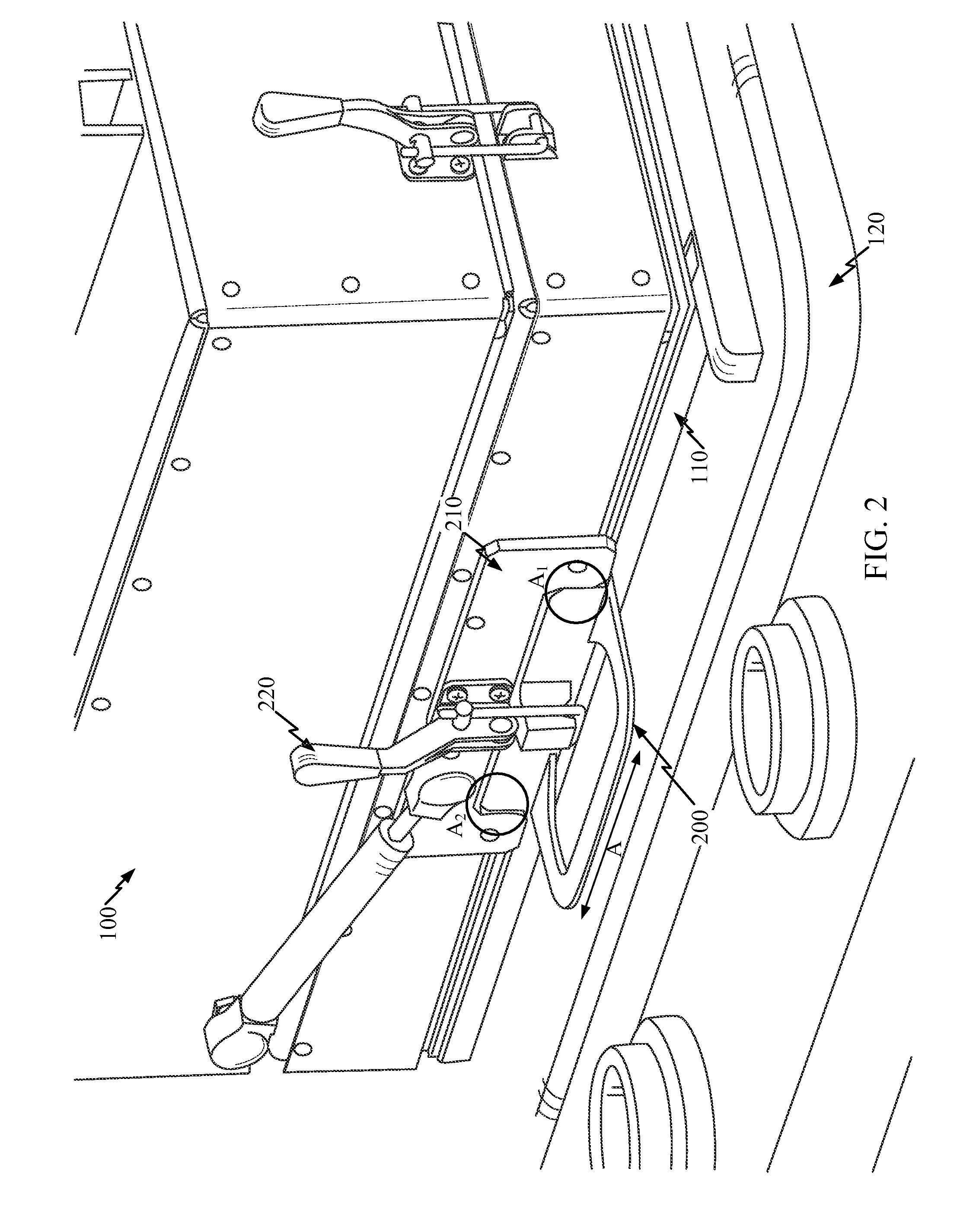
[0020]Turning now to FIG. 1 of the accompanying drawings, there is shown RF shielded enclosure 100 attached to Test Board Frame 110 which is supported by Tester 120. RF shielded enclosure comprises lid 101 and base 102.

[0021]RF shielded enclosure 100 is constructed using metal for the basic shape. Metal naturally restricts or attenuates the passage of EMI energy or RF energy. Metal is durable, inexpensive and relatively easy to form. Those skilled in the art would understand that other materials could be used.

[0022]RF shielded enclosure 100 is small enough and constructed out of appropria...


PUM


Abstract

An apparatus for restricting the flow of RF energy when attached to a tester wherein test equipment is positioned within the apparatus, comprising: a lid; a base; hinges for attaching the lid to the base; EMI gasket material for sealing seams; latches for attaching the lid to the base and for applying forces between the lid and the base to provide compression of the EMI gasket material for proper sealing of the seams; a connection point for providing two axis alignment of the base to the tester; and a positioning plate for providing three axis alignment of the test equipment in relation to the tester.

Description

FIELD[0001]This disclosure relates to the shielding of electronic equipment from electromagnetic interference (EMI). More particularly, there is presented a RF shielded enclosure that attaches to testers and allows for the use of automated as well as non-automated test equipment.BACKGROUND[0002]The manufacture and subsequent testing of electronic components generates electromagnetic energy at least in the form of radio frequency RF. The RF energy generated, if not shielded, emanates throughout the manufacturing building potentially causing interference to any of the activities in the building. RF energy from outside the manufacturing facility may also penetrate into the building and cause interference.[0003]One tool that is used to isolate a particular area within a RF rich environment is a screen room. These are large rooms covered entirely with costly RF shielding material such as copper mesh. They take a lot of time to build and consume valuable floor space. Over time the rooms d...

Claims


Application Information

Patent Timeline
Patent Type & Authority Patents(United States)
IPC IPC(8): H05K9/00
CPCG01R29/0814H05K9/0069G01R29/08H05K9/00
Inventor ALCALA, OSVALDO CDOUB, KENT STEVENELLIS, ROBERT WMARTINEZ, OCTAVIO DSUMNER, PATRICK
Owner QUALCOMM INC
Why Eureka
Try Eureka