
System and method for estimating electrical conduction delays from immittance values measured using an implantable medical device

a technology of impedance value and electrical conduction delay, which is applied in the field of implantable medical devices, can solve the problems of inconvenient and imprecise calibration of direct impedance-to-lap conversion procedures, increased conduction delays, and decreased impedance values, and achieves the effect of decreasing impedance values and increasing conduction delays

Inactive Publication Date: 2012-06-26
PACESETTER INC
View PDF43 Cites 30 Cited by
  • Summary
  • Abstract
  • Description
  • Claims
  • Application Information

AI Technical Summary

Problems solved by technology

In this regard, as the heart tends to enlarge, particularly with heart failure progression, conduction delays tend to increase, whereas impedance values tend to decrease.
Within at least some patients, calibrating a direct impedance-to-LAP conversion procedure can be inconvenient and imprecise.

Method used


Image

  • System and method for estimating electrical conduction delays from immittance values measured using an implantable medical device
  • System and method for estimating electrical conduction delays from immittance values measured using an implantable medical device
  • System and method for estimating electrical conduction delays from immittance values measured using an implantable medical device

Examples


Embodiment Construction

[0051]The following description includes the best mode presently contemplated for practicing the invention. The description is not to be taken in a limiting sense but is made merely for the purpose of describing the general principles of the invention. The scope of the invention should be ascertained with reference to the issued claims. In the description of the invention that follows, like numerals or reference designators will be used to refer to like parts or elements throughout.

Overview of Implantable Medical System

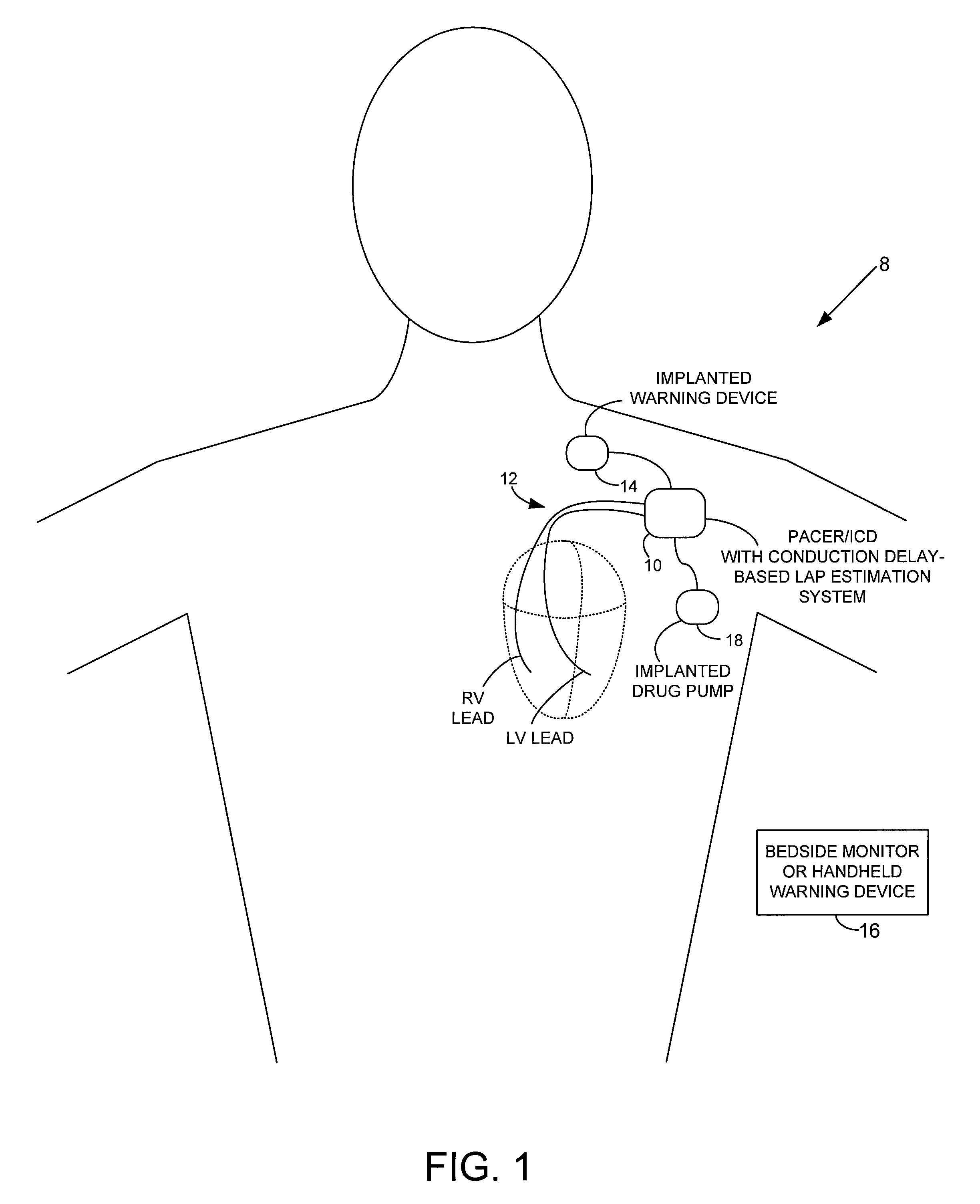
[0052]FIG. 1 provides a stylized representation of an exemplary implantable pacing medical system 8 capable of detecting electrical conduction delays within the heart of the patient and estimating LAP based on the conduction delays. To this end, implantable system 8 includes a pacer / ICD 10 or other cardiac stimulation device that incorporates internal components (shown individually in FIG. 15, and discussed below) for detecting one or more conduction delays using elec...


PUM


Abstract

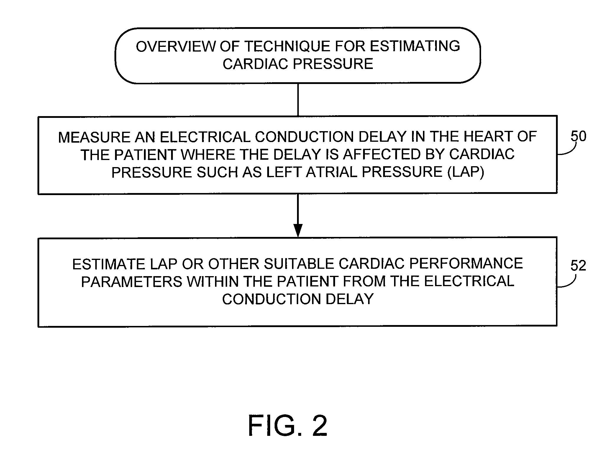
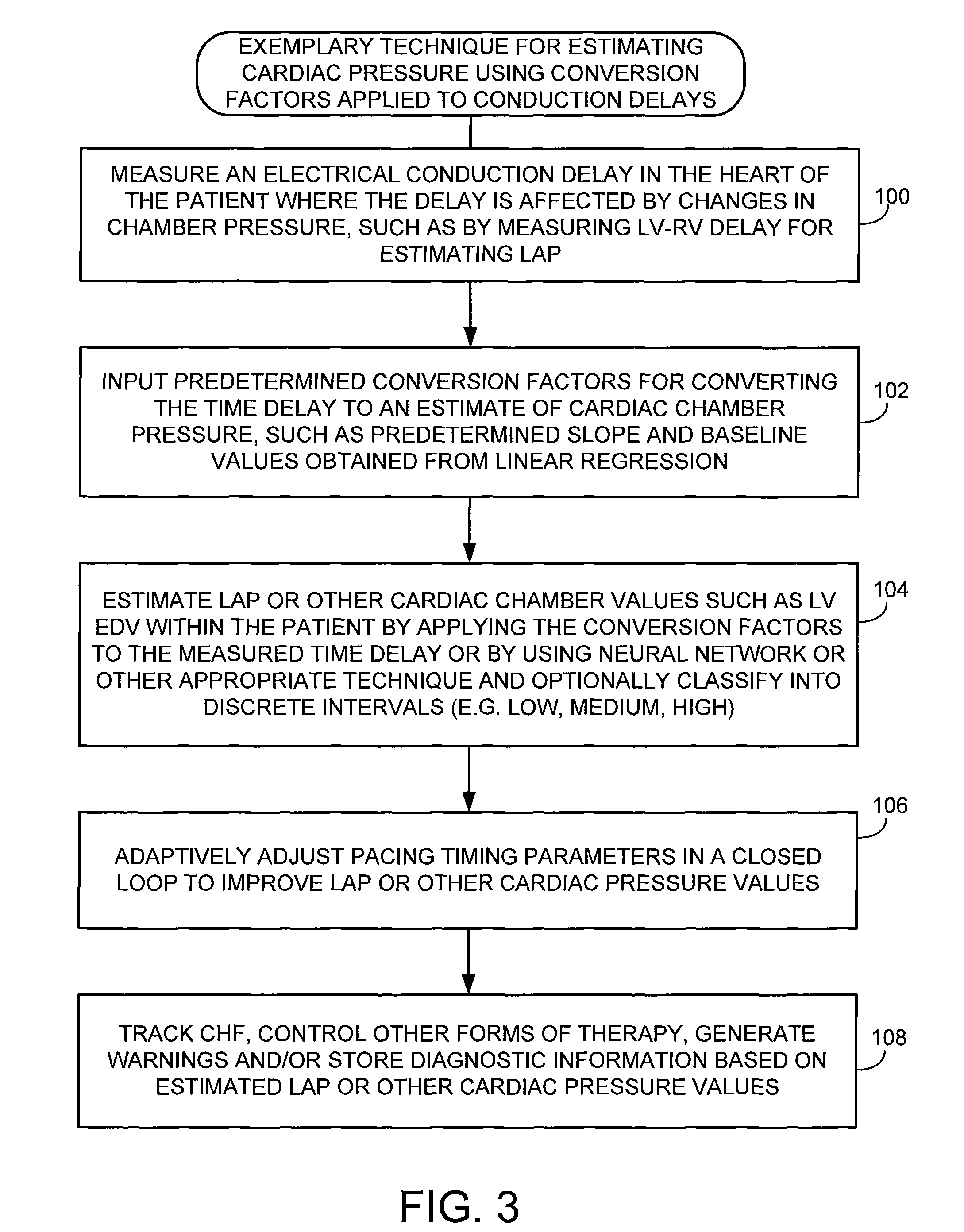
Techniques are provided for estimating electrical conduction delays with the heart of a patient based on measured immittance values. In one example, impedance or admittance values are measured within the heart of a patient by a pacemaker or other implantable medical device, then used by the device to estimate cardiac electrical conduction delays. A first set of predetermined conversion factors may be used to convert the measured immittance values into conduction delay values. In some examples, the device then uses the estimated conduction delay values to estimate LAP or other cardiac pressure values. A second set of predetermined conversion factors may be used to convert the estimated conduction delays into pressure values. Techniques are also described for adaptively adjusting pacing parameters based on estimated LAP.

Description

RELATED APPLICATIONS[0001]This application is a continuation-in-part of U.S. patent application Ser. No. 11 / 779,350, of Wenzel et al., filed Jul. 18, 2007, entitled, “System and Method for Estimating Cardiac Pressure based on Cardiac Electrical Conduction Delays using an Implantable Medical Device,” which claimed priority on U.S. Provisional Patent Application No. 60 / 910,060 of Wenzel et al., entitled, “System and Method for Estimating Left Atrial Pressure based on Intra-Cardiac Conduction Time Delays,” filed Apr. 4, 2007, which are both fully incorporated by reference herein. This application is also related to U.S. patent application Ser. No. 11 / 779,380, of Wenzel et al., entitled, “System and Method for Estimating Cardiac Pressure based on Cardiac Electrical Conduction Delays using an Implantable Medical Device,” filed Jul. 18, 2007.FIELD OF THE INVENTION[0002]The invention relates generally to implantable medical devices such as pacemakers and implantable cardioverter defibrilla...

Claims


Application Information

Patent Timeline
Patent Type & Authority Patents(United States)
IPC IPC(8): A61B5/04
CPCA61B5/0215A61B5/053A61N1/36521A61B5/742A61B5/7405A61B5/7282A61B5/7278A61B5/686A61B5/4839A61B5/0002A61B5/746A61B5/002A61B2560/0223
Inventor WENZEL, BRIAN JEFFREYPANESCU, DORINNAWARE, MIHIRSIOU, JEFFERY
Owner PACESETTER INC
Learn More