Base/lifting structure

a technology of lifting structure and base rail, which is applied in the direction of machine supports, furniture parts, other domestic objects, etc., can solve the problem of large weight that cannot be lifted without the base rails yielding

Active Publication Date: 2012-07-03
AAF MCQUAY INC
View PDF8 Cites 12 Cited by
  • Summary
  • Abstract
  • Description
  • Claims
  • Application Information

AI Technical Summary

Benefits of technology

[0004]The present invention is a design for a lifting structure that is made of formed sheet metal which is bolted together. The main advantage for this type of lifting member is that it is made from formed sheet metal and requires no welding. When constructed these brackets become a “box in box” design. This achieves significant strength in all moment directions. By connecting the lifting bracket directly though the base structure it is able to resist the common “twist out” moment on the base channels.
[0007]The lifting bracket allows for safe attachment from several types of rigging equipment including shackles, hooks, and locking hooks. The units can then be lifted using straps, cables, or chains rated for weight. The shorter span between lift points allows the lift angle to be less which decreases the tension needed from the rigger to lift the unit. The shorter span also allows the unit to be counterweighted by its own mass. This counterweight means a large amount of weight can be lifted without the base rails yielding. With this the main base channel was able to be split into two members so the factory can better handle the parts.
[0008]This lifting design allows for all of the variations in the McQuay Vision AHU including height, length and width. This type of structure is significantly safer than the current Vision rigging design and will incorporate itself well in the extended vision units especially because the sections can be nearly double the current max weight. The bracket extends beyond the edge of the unit to protect the splice collar and the ceiling of the unit resulting in less installation damage. This lifting design offers a competitive advantage against custom AHU manufacturers without adding structural steel or making any heavier components than used today.

Problems solved by technology

This counterweight means a large amount of weight can be lifted without the base rails yielding.

Method used


Image

  • Base/lifting structure
  • Base/lifting structure
  • Base/lifting structure

Examples


Embodiment Construction

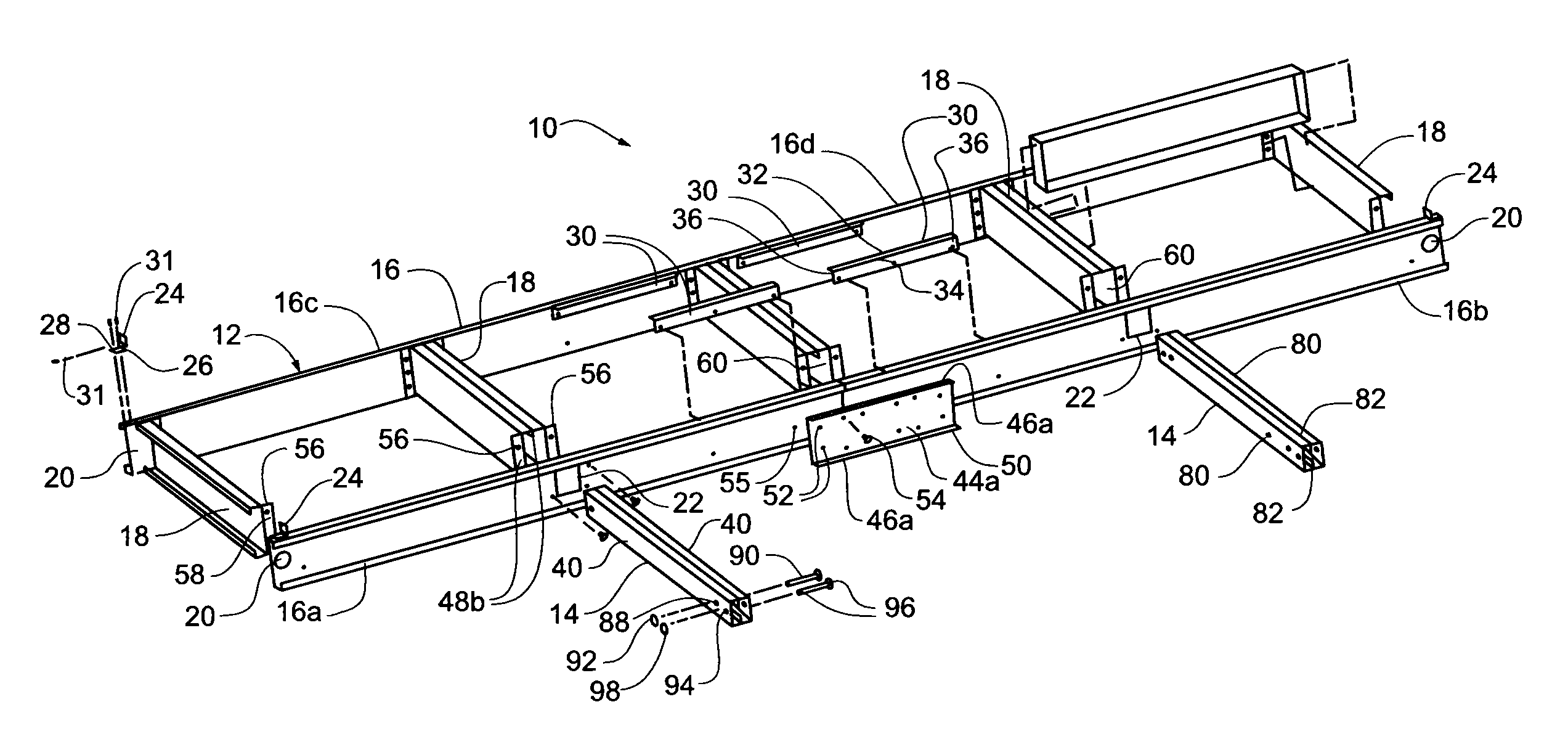
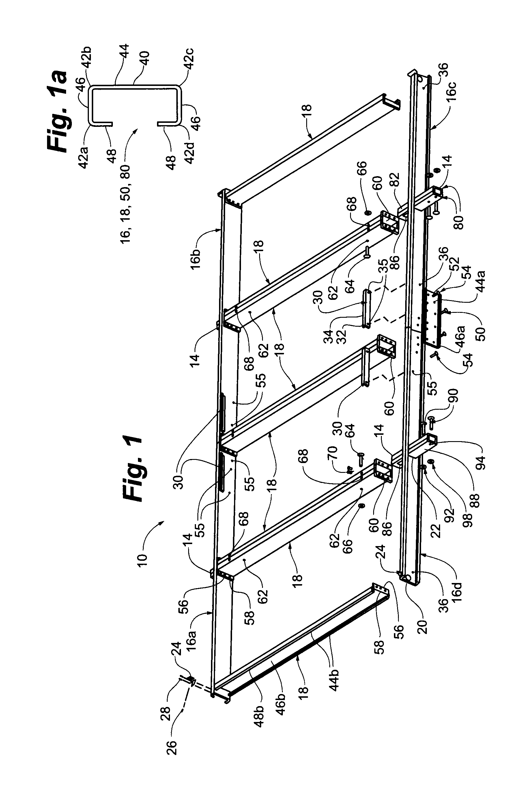
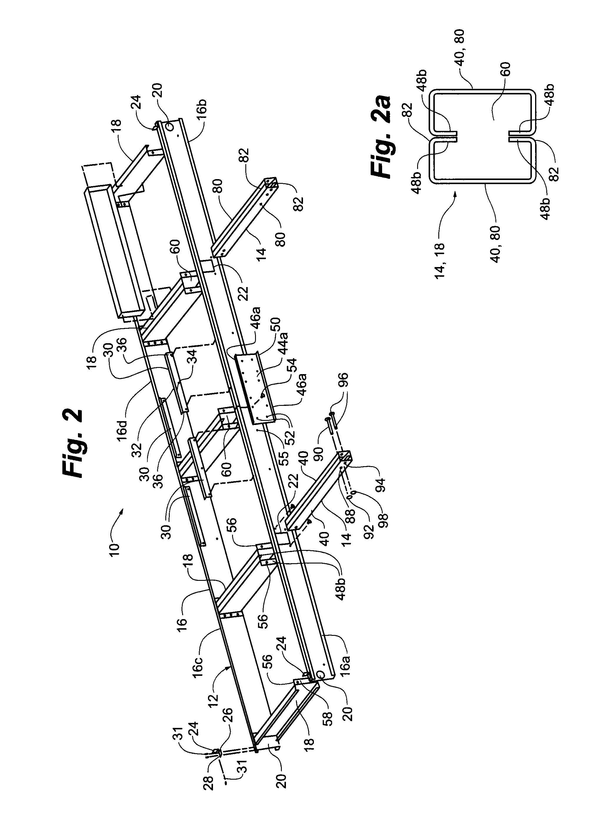
[0017]The base / lifting structure of the present invention is shown generally at 10 in the figures. The base / lifting structure 10 effectively performs two functions with regard to a commercial HVAC unit 102. The first function is as a means to lift an HVAC unit 102 for disposing the HVAC unit 102 on a truck bed or a transport. (See FIG. 3.) Additionally, an HVAC unit 102 may be lifted by a crane or the like being coupled to the base / lifting structure 10 for disposition on the roof of a building.

[0018]The second function that the base / lifting structure 10 performs is as a base for the HVAC unit 102 once the HVAC unit 102 is positioned in place on the roof of the building.

[0019]It should be noted that all of the structure elements of the base / lifting structure 10 are formed of galvanized sheet metal that has four bends to define a C-shape in cross section. In the past, bases for HVAC units 102 have been formed of welded structure. The structural elements of the present invention are re...


PUM

PropertyMeasurementUnit
lengthaaaaaaaaaa
dimensionsaaaaaaaaaa
strengthaaaaaaaaaa

Abstract

A base / lifting structure, includes a base frame assembly and a plurality of readily removable lifting bracket channels, the base frame assembly and a plurality of readily removable lifting bracket channels each having structural elements, the structural elements being formed of galvanize sheet metal formed in a C-shape cross section, the structural elements being selectively utilized in the base frame assembly singly and in pairs. A method of forming a base / lifting structure is further included.

Description

RELATED APPLICATION[0001]This application claims the benefit of U.S. Provisional Application No. 61 / 012,201 filed Dec. 7, 2007, and incorporated herein in its entirety by reference.FIELD OF THE INVENTION[0002]This invention relates generally to improvements in structures and apparatus used primarily in the field of handling HVAC components, and more particularly to a lifting structure, and its particular combination of elements, that provide a unique cooperation of such elements for raising through a rigging system large HVAC components to a desired operating position proximate a structure. While the particular structure disclosed herein is directed primarily to equipment used in the building industry, it will be understood that this invention is capable of being used in other allied fields such as warehousing for raising material to be stored in bins and elevated positions, truck and aircraft loading, and the like.BACKGROUND OF THE INVENTION[0003]There is a need for an efficient wa...

Claims


Application Information

Patent Timeline
Patent Type & Authority Patents(United States)
IPC IPC(8): B65D19/00
CPCF16M5/00
Inventor SMALL, JEREMY
Owner AAF MCQUAY INC
Why Eureka
Try Eureka