Ammeter with improved current sensing

a current sensing and ammeter technology, applied in the field of ammeters, can solve the problems of mechanical complexity of opening and closing the hinged core, the weight of the iron core, and the inability to simply be placed around the conductor to be measured, so as to prevent display

Active Publication Date: 2012-07-03
GREENLEE TEXTRON
View PDF18 Cites 17 Cited by
  • Summary
  • Abstract
  • Description
  • Claims
  • Application Information

AI Technical Summary

Benefits of technology

[0012]The present invention avoids the disadvantages of prior ammeters, while affording additional structural and operating advantages.
[0013]An aspect of the invention is the provision of an ammeter which defines a sensing region, provides accurate measurement of current flowing in a conductor extending through the sensing region, and senses whether or not the conductor extends through the sensing region.
[0018]In accordance with a further embodiment of the invention, a method is provided for measuring current flow in a conductor. The method includes the steps of sensing the magnitude of the current flowing in the conductor, defining a sensing region, sensing whether or not the conductor extends through the sensing region, displaying the sensed current magnitude if the conductor extends through the sensing region, and preventing display of the sensed current magnitude if the conductor does not extend through the sensing region.

Problems solved by technology

The primary disadvantage of using a toroidal magnetic iron core current transformer in pre-existing circuits is that it cannot simply be placed around the conductor to be measured.
For this reason, current transformers of this type are generally restricted to laboratory use.
As a practical matter however, the mechanical complexity of opening and closing the hinged core and the weight of the iron core are substantial disadvantages for a tool to be used in the field.
Rogowski coils provided with a permanent opening so as to allow the coil to be placed conveniently over or around the conductor to be measured suffer from reduced accuracy and consistency, in that the measured current can vary with the position of the conductor to be measured relative to the opening in the Rogowski coil.
While this construction allows great flexibility in design and low-cost construction, it has considerable disadvantages in terms of how the conductor to be measured must be centered with respect to the cluster of individual coils, and it still allows substantial influence of conductors outside of the cluster of individual coils.
While these two improvements do allow for convenience of use and for compact and lightweight construction, neither of them equals the performance of a closed Rogowski coil or of an iron core current transformer, with their accurate measurement of conductors inside the core / coil and high degree of rejection of conductors outside the core / coil.
Such ammeters suffer from the disadvantages discussed above, with respect to Rogowski coils having a permanent opening.
Furthermore, in hot-stick applications, wherein the user may be positioned at some distance from the conductor or power line, the current of which is to be measured, it is frequently difficult to tell whether or not the conductor is positioned relative to the sensing head so as to ensure accurate current measurement.
Thus, the user may not be sure whether or not the displayed current reading is an accurate reading.

Method used


Image

  • Ammeter with improved current sensing
  • Ammeter with improved current sensing
  • Ammeter with improved current sensing

Examples


Embodiment Construction

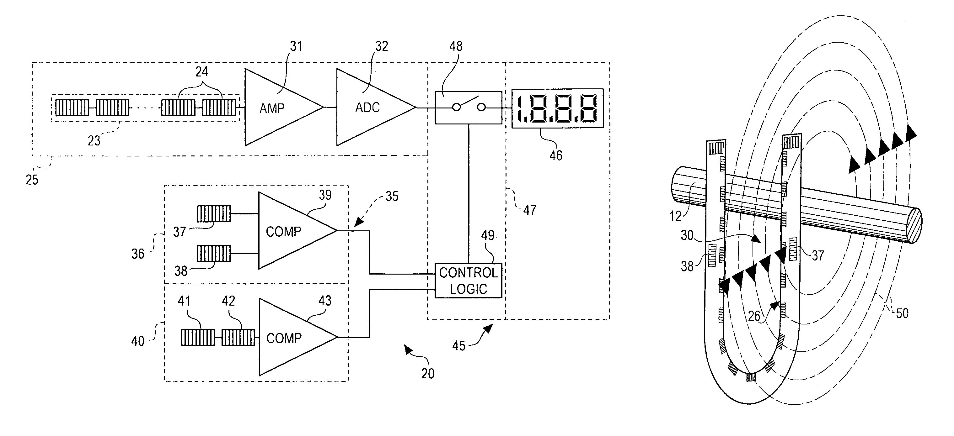
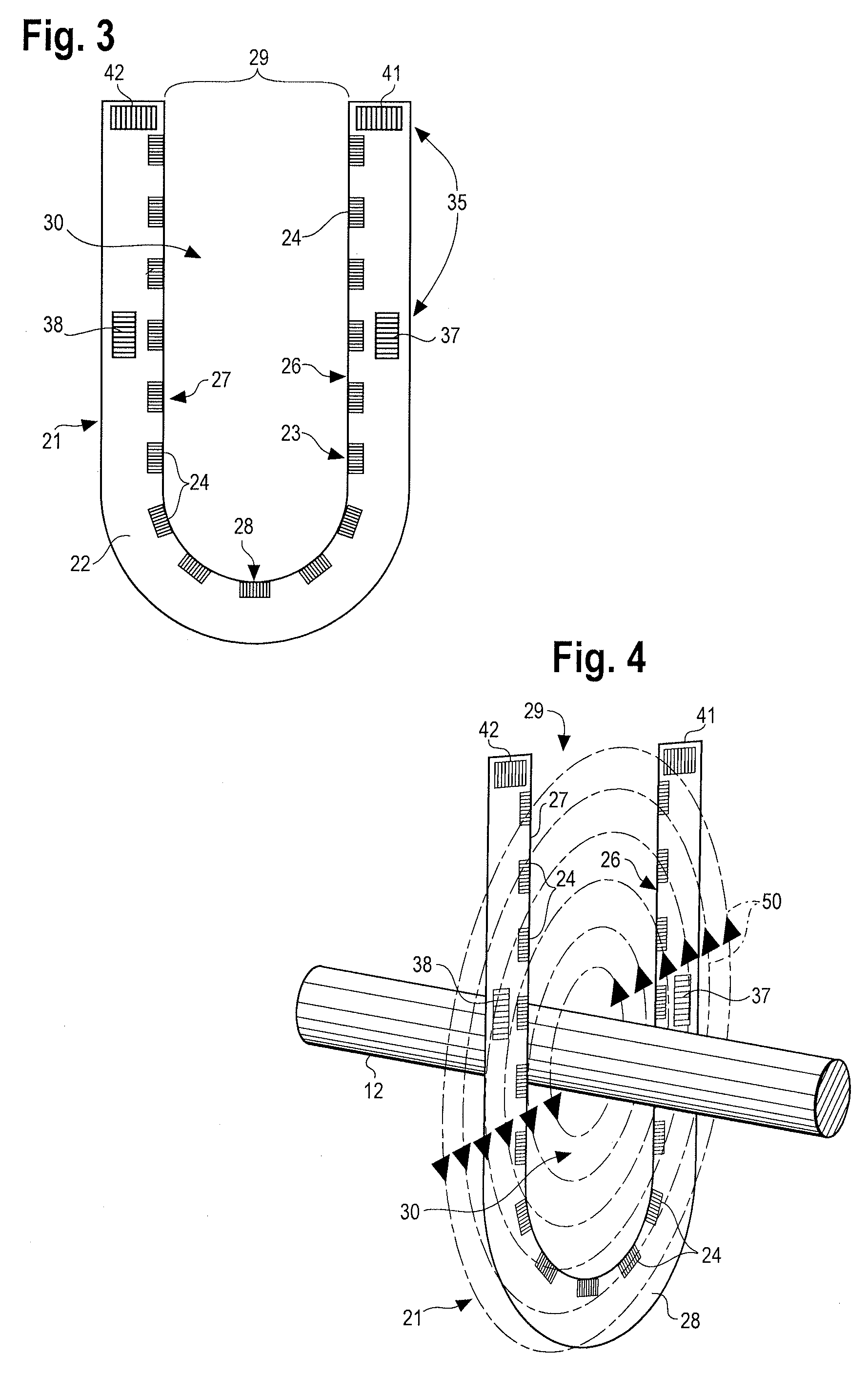
[0027]Referring to FIG. 2, there is illustrated an ammeter, generally designated by the numeral 20, constructed in accordance with and embodying the features of the present invention. Referring also to FIG. 3, the ammeter 20 includes a sensing head 21, which includes a generally U-shaped substrate 22, which may be in the form of a printed circuit board, and will typically be disposed in a suitable U-shaped housing (not shown). The sensing head 21 carries a current-sensing coil structure 23 which includes a plurality of coils 24 arranged in a linear array extending along the U-shaped substrate 22 to form a generally U-shaped array including legs 26 and 27 interconnected at one end thereof by a bight 28. The opposite ends of the legs are spaced apart by a gap 29. The coils 24 of the current-sensing coil structure 23 are interconnected, as by printed circuitry, and form a part of a current-detecting circuit 25 (FIG. 2). The U-shaped array defines a sensing region 30 extending between t...


PUM


Abstract

An ammeter is provided with a plurality of individual wound coils interconnected in a generally U-shaped array to measure the magnitude of current in a conductor extending through a sensing region inside the U-shape. Additional pairs of position-sensing coils determine the position of the conductor relative to the sensing region and provide outputs to circuitry which permits the magnitude measurement to be displayed only if the conductor extends through the sensing region.

Description

TECHNICAL FIELD[0001]This application relates to ammeters, and has particular application to ammeters for use with high-voltage circuits, such as those found in electric power transmission and distribution systems, although the principles of the invention have applicability to low-voltage circuits, as well.BACKGROUND[0002]The generally accepted method for accurately measuring power frequency AC currents uses a current transformer. A current transformer is generally a toroid-shaped magnetic core with windings around the core, typically about 100 turns or more. The magnetic core is constructed of some ferrous material or alloy. In use, the conductor, the current in which is to be measured is passed through the hole in the center of the toroidal magnetic core. The current flowing in the conductor to be measured generates a magnetic field, which is captured within the magnetic toroid of the current transformer which surrounds it. This magnetic field induces a current in the windings aro...

Claims


Application Information

Patent Timeline
Patent Type & Authority Patents(United States)
IPC IPC(8): G01R7/00
CPCG01R15/181G01R1/06772G01R1/06788G01R1/07G01R15/125
Inventor MCNULTY, WILLIAM J.BUCHANAN, JAMES S.MCNULTY, CONNOR M.
Owner GREENLEE TEXTRON
Why Eureka
Try Eureka