Two-piece protective carrying case

a protective case and two-piece technology, applied in the field of electronic device cases, can solve the problems of increasing production costs, multi-step processes, slow production time, etc., and achieve the effect of avoiding disadvantages and additional structural and operating advantages

Active Publication Date: 2012-10-16
UNCOMMON
View PDF9 Cites 137 Cited by
  • Summary
  • Abstract
  • Description
  • Claims
  • Application Information

AI Technical Summary

Benefits of technology

[0008]There is disclosed herein an improved protective carry case for a device, such as a portable electronic device (e.g., a phone, camera, PDA, etc.) which avoids the disadvantages of prior devices while affording additional structural and operating advantages.
[0011]It is another aspect of an embodiment of the invention to provide at least one stop on the inner surface of the case for frictionally engaging another surface, such as that of the portable device to be encased. In the event a camera or other sound or image recording device is provided by the portable device, it is an aspect of an embodiment of the invention to provide a passage having an opening on each of the back surface and the inner surface of one of either the first body section or the second body section, the openings being connected by a sidewall. The sidewall is preferably slanted outward to lessen possible interference with the image and / or sound recording function.

Problems solved by technology

However, these multi-step processes have a number of significant drawbacks.
First, the added steps typically slow production time and increase production cost.
Second, subjecting the item to repeated high-temperature steps can have a detrimental effect on the item.
The multiple steps and molding devices required for each step significantly increases the complexity of the process and the costs for producing the final item with an image or design printed thereon.
That is, when a sheet of material is positioned within the heat treatment device to finalize the transfer of the dye printing onto the item, often times the process results in a partial or complete deformation or destruction of the original detail from the initial thermoforming steps.
That is, due to the repeated use of high-temperatures necessary to initiate transfer of the dye from a pre-printed film to one or both sides of the thermoformed item, the edges around the item may be unable to withstand such heat for the required duration of the transfer process.
However, shortened heat transfer times would fail to ensure consistent transfer of the dye on the entire surface of the item.
Thus, the resulting item may often be undesirable or unusable for its intended purpose due to the damage done to the thermoform details on the item.

Method used


Image

  • Two-piece protective carrying case
  • Two-piece protective carrying case
  • Two-piece protective carrying case

Examples


Embodiment Construction

[0023]While this invention is susceptible of embodiment in many different forms, there is shown in the drawings and will herein be described in detail a preferred embodiment of the invention with the understanding that the present disclosure is to be considered as an exemplification of the principles of the invention and is not intended to limit the broad aspect of the invention to embodiments illustrated.

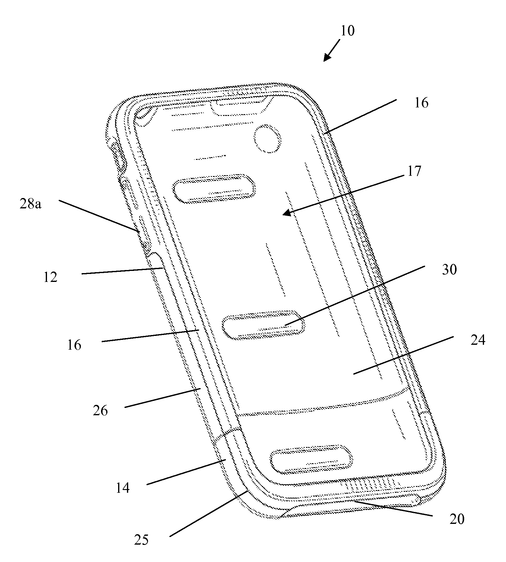
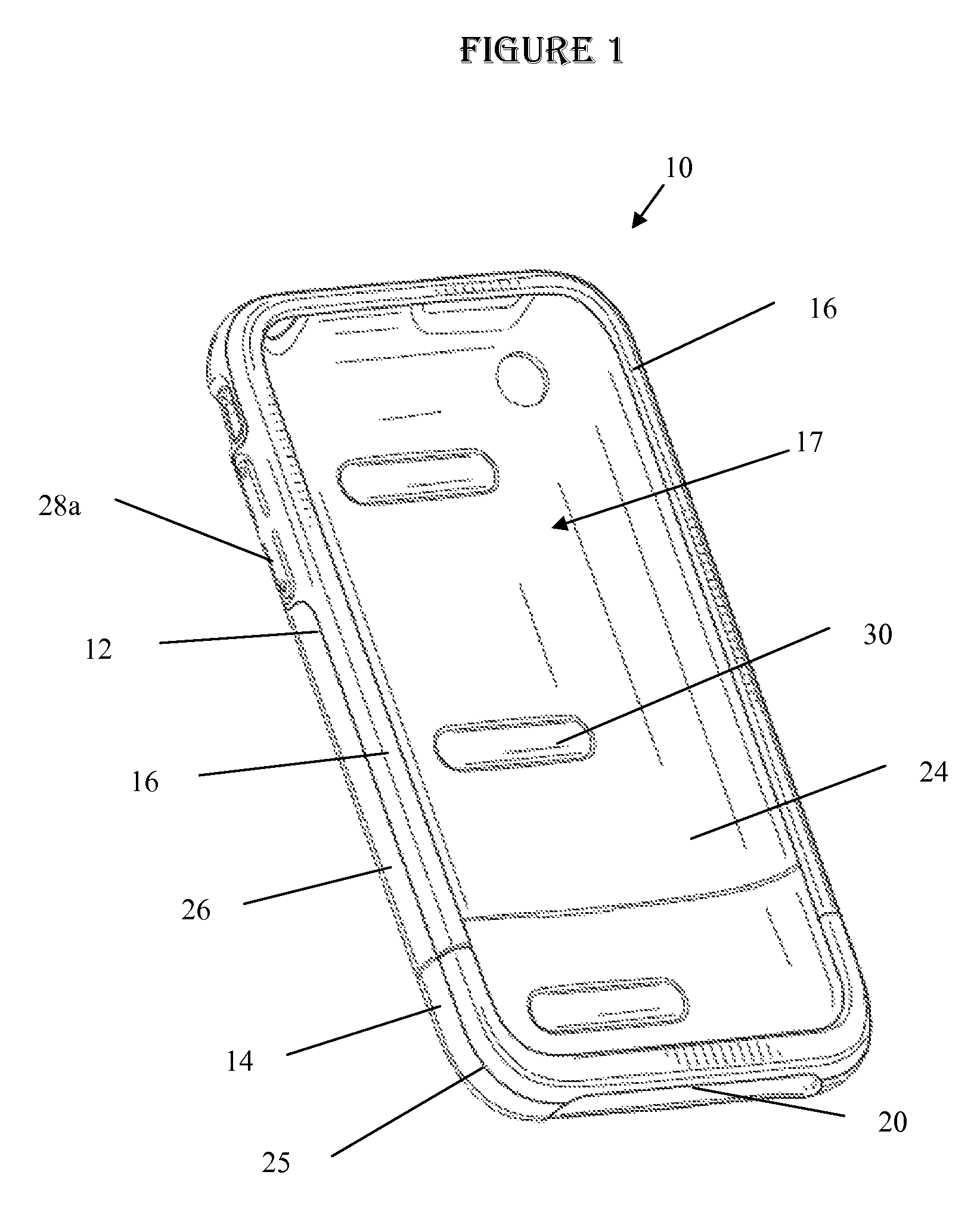
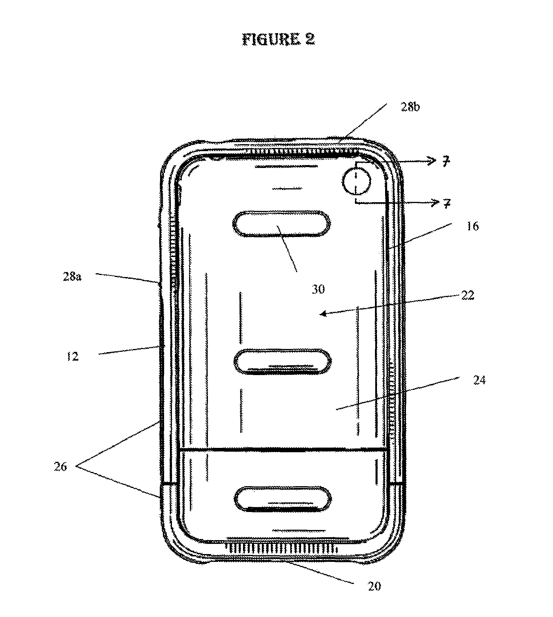
[0024]Referring to FIGS. 1-9, there is illustrated an embodiment of a protective carrying case, generally designated by the number 10, for a portable electronic device. The particular illustrated embodiment is representative of a carrying case designed for an iPhone, manufactured by Apple, Inc. However, a carrying case 10 made in accordance with the present invention may be configured to fit any number of portable electronic devices, including other smart phones, PDA devices, calculators, cameras, global positioning system (GPS) devices, and the like. Those skilled in the relevant ...


PUM

PropertyMeasurementUnit
temperaturesaaaaaaaaaa
lengthaaaaaaaaaa
colorsaaaaaaaaaa

Abstract

A carrying case for a portable device is disclosed. Generally speaking, the protective case for a portable device comprises a first body section and a second body section, each having a back surface and upturned sides, and a rim affixed to an edge of the upturned sides of the body sections, the rim defining an open area. Preferably, the first and second body sections are of contrasting colors and connect to one another to form a cavity defined by the respective back surfaces and upturned sides. Further, the first and second body sections and the first and second rim are preferably all formed of the same material.

Description

RELATED APPLICATIONS[0001]The present application claims the filing priority of, and incorporates herein by reference, Provisional Application No. 61 / 233,146, filed on Aug. 12, 2009.TECHNICAL FIELD[0002]The present invention relates to electronic device cases, and more specifically to thermoformed protective cases formed with two-piece resins to ensure high quality registration of features on one or both sides of the item.BACKGROUND OF THE INVENTION[0003]Previously, to produce thermoformed items having details disposed on one or both sides of the item, using a plastic or other suitable material, required the use of different and multiple molding processes. For example, a sheet of material or fluid material from which an item was to be formed might be initially positioned within or directed into an injection or compression molding device in order to create detail or features required on at least one side of the item. Subsequently, the material sheet would then be positioned or run th...

Claims


Application Information

Patent Timeline
Patent Type & Authority Patents(United States)
IPC IPC(8): B65D85/00B65D85/30
CPCA45C11/00H04B1/3888Y10T29/49895A45C2011/002A45C13/08B28B11/001B41M5/035B41M5/382B41M5/41B41M5/52B44C1/16B44C1/165B44C1/1712B65D81/02
Inventor WILSON, SCOTTBROWN, DUSTINGODSTON, JON
Owner UNCOMMON
Why Eureka
Try Eureka