Fault location

a technology for fault locations and telecommunications networks, applied in data switching networks, frequency-division multiplexes, instruments, etc., can solve problems such as inability to routinely check all network connections very frequently, total loss of service, and inconvenience for customers, so as to reduce the number of staff needed in customer contact centers to handle fault reports, reduce service downtime, and resolve problems potentially much faster

Active Publication Date: 2012-07-03
BRITISH TELECOMM PLC
View PDF15 Cites 8 Cited by
  • Summary
  • Abstract
  • Description
  • Claims
  • Application Information

AI Technical Summary

Benefits of technology

This patent describes an innovative method that allows customers to detect and notify network providers about technical problems they encounter on their devices. Instead of having to manually call or email the company, this system works by monitoring customer activity and reporting back to the provider when there's something wrong. This saves time and reduces the amount of people required to fix issues. Additionally, it helps identify where the issue is located faster, allowing the provider to address it quicker and minimizing downtime for users.

Problems solved by technology

The technical problem addressed in this patent text relates to identifying and locating failures in computer networks quickly enough to prevent discomfort or even damage to consumers who rely on these services. Current methods involve waiting for customers to report issues, leading to delays in identification and potential downtime for repairs. Additionally, there are challenges related to determining whether a specific issue affects just one person or multiple people simultaneously.

Method used


Image

  • Fault location
  • Fault location
  • Fault location

Examples


Embodiment Construction

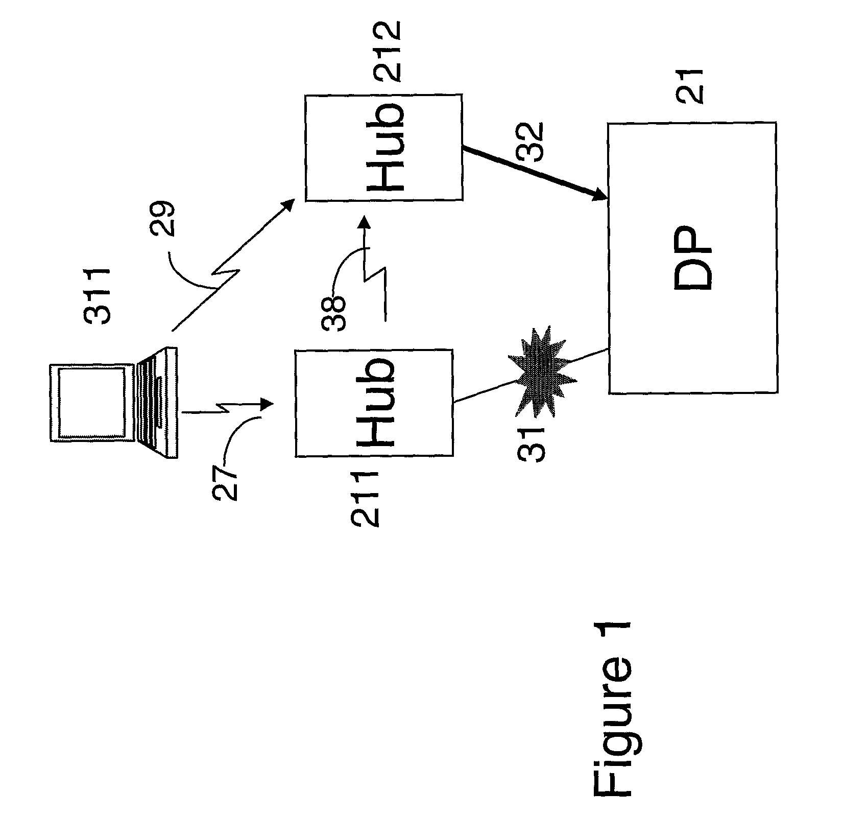
[0027]FIG. 1 illustrates a computer 311 which can be connected to the network through a WI-FI connection 27 to a wireless hub. However, if the intended hub 211 has lost its connection 31 to the network, the computer 311 may connect to another nearby hub 212 instead. If the first hub 211 is still operational, such a connection might be realized by a wireless connection 38 between the two hubs 211, 212. Alternatively, a direct wireless connection 29 may be established between the terminal 311 and the neighboring hub 212.

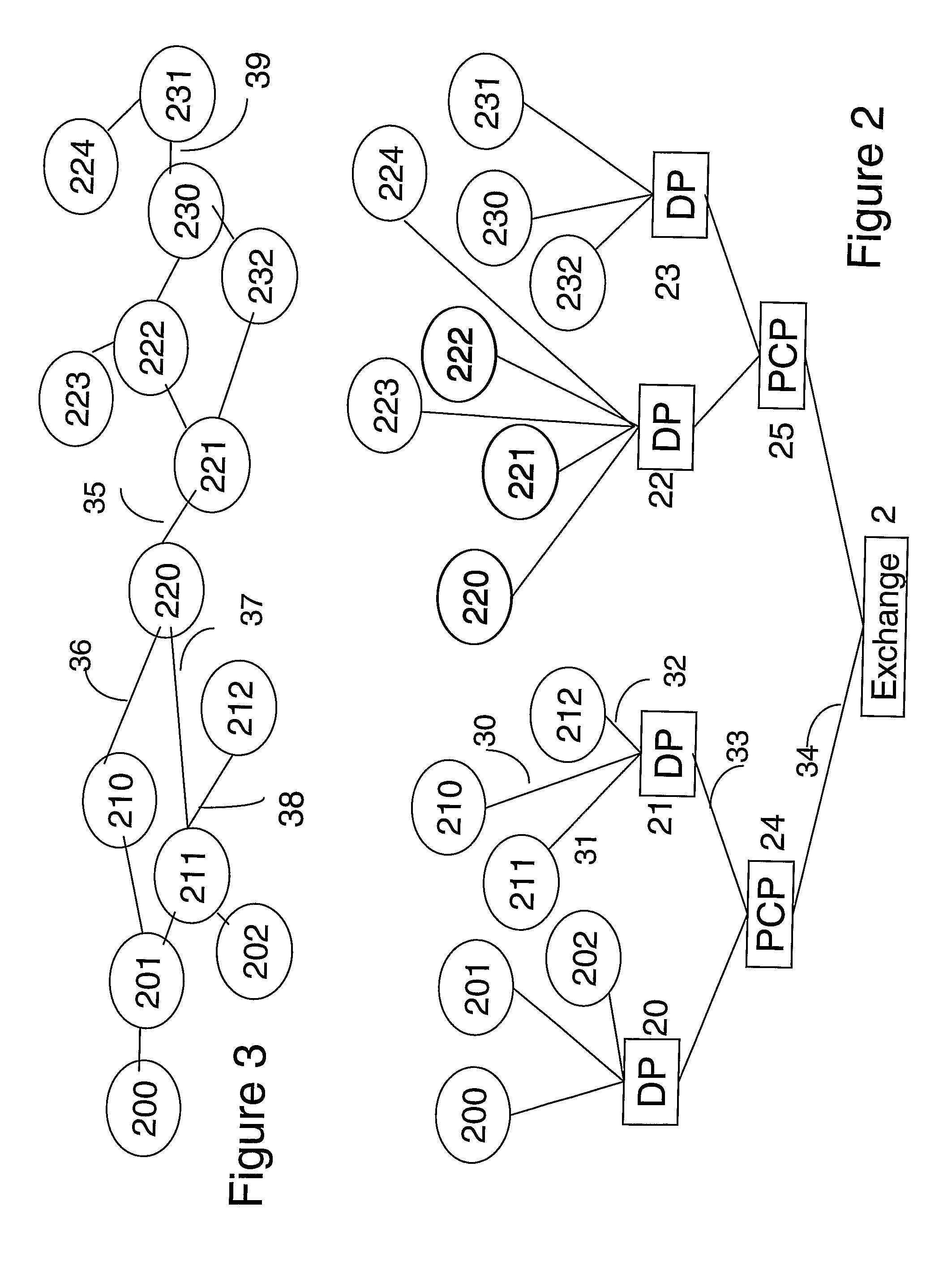
[0028]FIG. 2 illustrates a plurality of computing devices 200-202, 210-212, 220-224, 230-232, of which the hub 211 depicted in FIG. 1 is a member, each operating as a communication node (typically a WI-FI access point) connected to the Internet, e.g. via a broadband connection to an exchange 2. The connections follow a branched structure. For example, as already described with reference to FIG. 1, nodes 211, 212 are each connected by respective cables 31, 32 to a distr...


PUM


Abstract

Each node in a hierarchical network regularly checks to determine whether its network connection is intact. If not, it autonomously communicates with other nodes in the physical neighborhood, using wireless capability also included at each node. It first searches for a wireless path to its immediate neighbors in the hierarchy attempting to reach a working node connected to the same distribution point. The nodes collect, store and exchange connectivity data on neighboring nodes. One member of a group of nodes that have exchanged connectivity information is selected to transmit a connectivity report to network control center. If not itself connected to the hierarchical network, the selected node can use the connection to the closest working node and its broadband connection to the network control center to inform the network operator of the fault and its likely location.

Description


Claims


Application Information

Patent Timeline
Owner BRITISH TELECOMM PLC
Why Eureka
Try Eureka