

Sliding valve
- Summary
- Abstract
- Description
- Claims
- Application Information
AI Technical Summary
Benefits of technology
Problems solved by technology
Method used
Image

Examples
Embodiment Construction
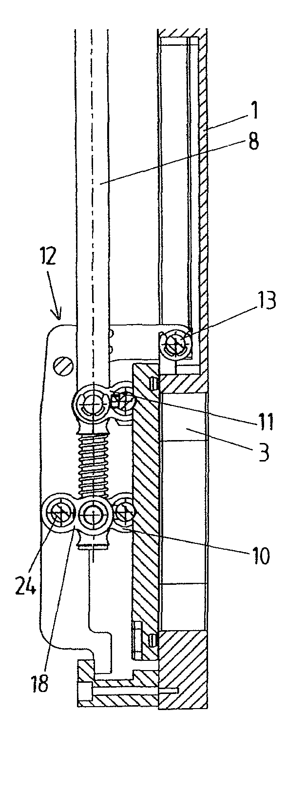
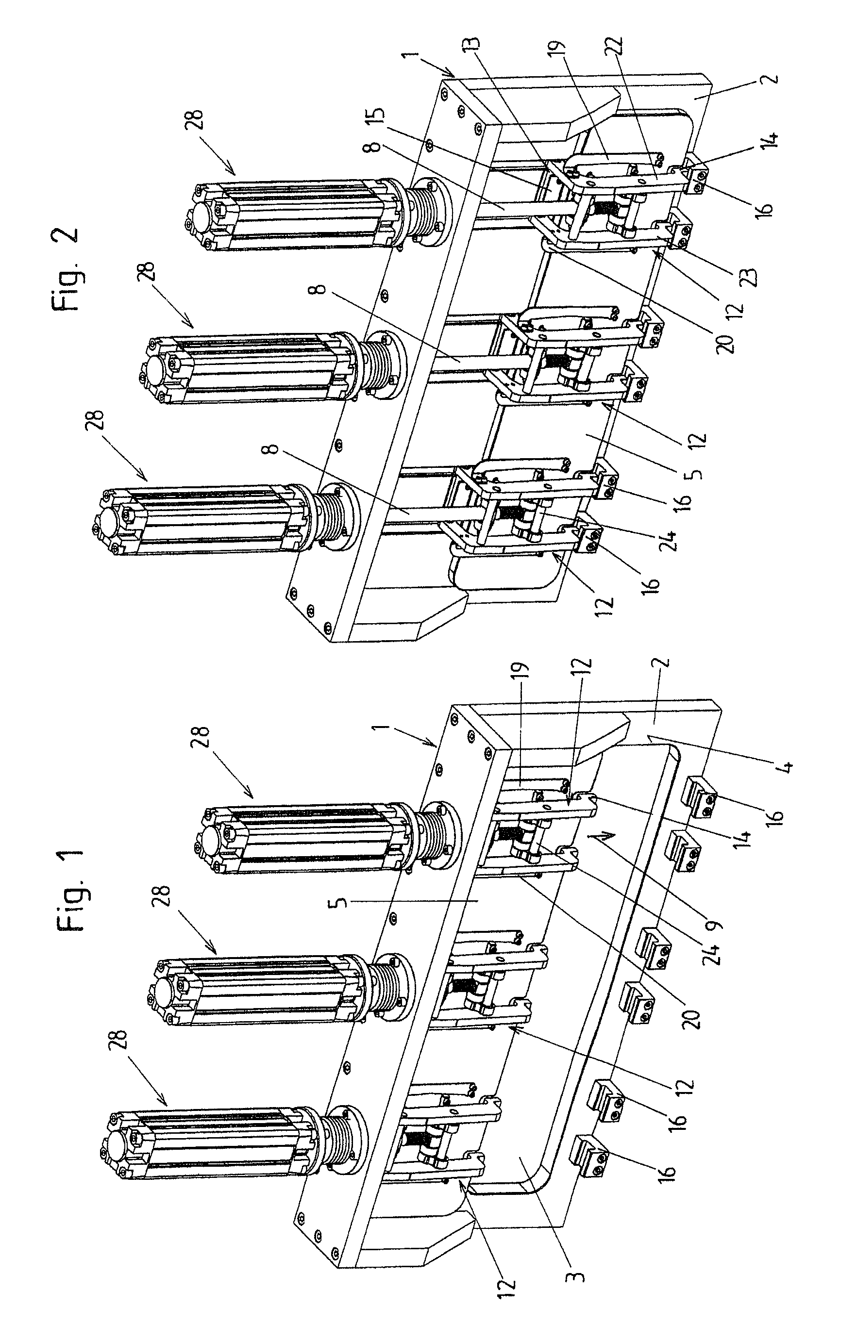
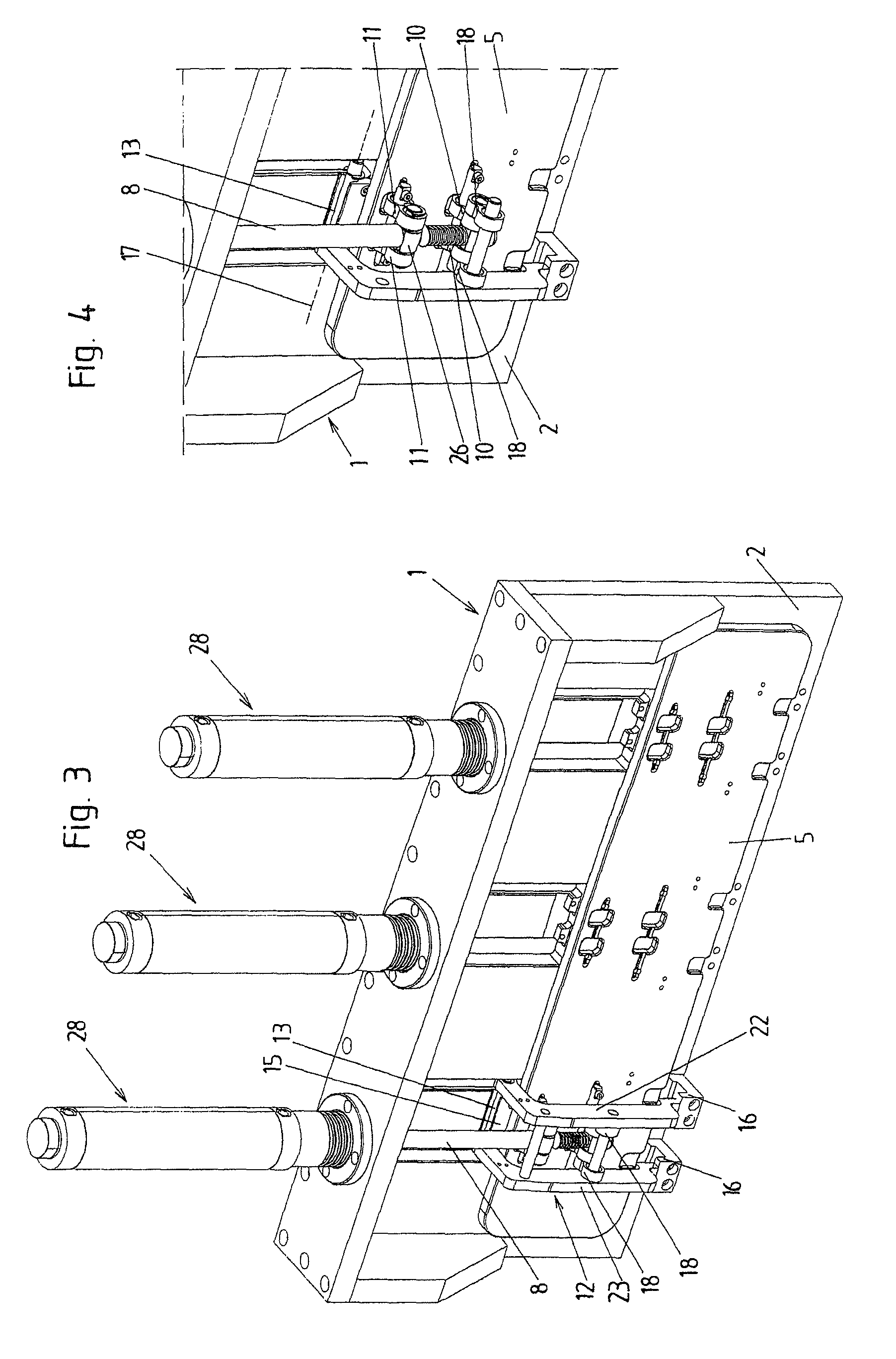
[0040]A preferred embodiment of a sliding valve or plate valve provided for vacuum applications according to the invention will be explained below with reference to FIGS. 1 to 13. The sliding valve has a valve body 1 that has a wall 2 with a valve opening 3. In the closed state of the valve, a valve plate 5 is pressed onto the valve seat 4 surrounding the valve opening 3, in order to seal the valve opening 3 vacuum-tight using a sealing ring 6 made from an elastic material, for example, Viton®. The sealing ring 6 is arranged on the valve plate 5 in the illustrated embodiment and is pressed onto a sealing face of the valve seat 4. It is also conceivable and possible to arrange the sealing ring 6 on the valve seat 4 and the sealing face on the valve plate 5.
[0041]In the opened state of the sliding valve (FIGS. 1, 6, and 10), the valve plate 5 frees the valve opening 3, wherein it is advantageously arranged completely next to the valve opening 3 viewed in the direction of the axis 7 of...
PUM
 Abstract
Description
Claims
Application Information