Luminous keyboard assembly

a keyboard and luminous technology, applied in the field of keyboard assembly, can solve the problems of inconvenient operation under dark conditions and high cos

Inactive Publication Date: 2012-07-10
HON HAI PRECISION IND CO LTD
View PDF3 Cites 14 Cited by
  • Summary
  • Abstract
  • Description
  • Claims
  • Application Information

AI Technical Summary

Benefits of technology

[0005]A typical keyboard assembly does not have the function to illuminate itself, which makes it inconvenient to operate under dark conditions. At present, there are luminous keyboard assemblies which can illuminate themselves. A first kind of luminous keyboard assembly includes a keyboard module with a plurality of keys and a backlight module under the keyboard module. When the backlight module is turned on, the keyboard module illuminates all the keys. A second kind of luminous keyboard assembly includes a keyboard module with a plurality of keys and a plurality of light sources. Each light source illuminates each key independently. When a given key is pressed, a corresponding light source is turned on and then illuminates the given key. The first kind keyboard assembly can not selectively illuminate a single key. However, the second kind of keyboard assembly requires a large amount of light sources to light each key, so the cost will be expensive.

Problems solved by technology

A typical keyboard assembly does not have the function to illuminate itself, which makes it inconvenient to operate under dark conditions.
However, the second kind of keyboard assembly requires a large amount of light sources to light each key, so the cost will be expensive.

Method used


Image

  • Luminous keyboard assembly
  • Luminous keyboard assembly
  • Luminous keyboard assembly

Examples


first embodiment

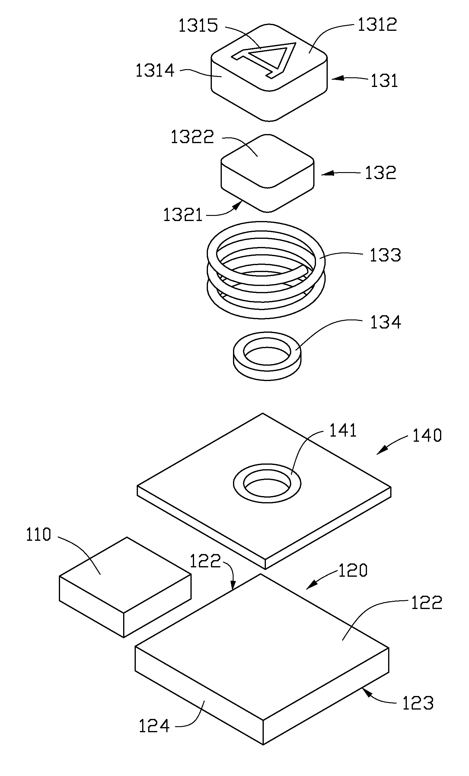
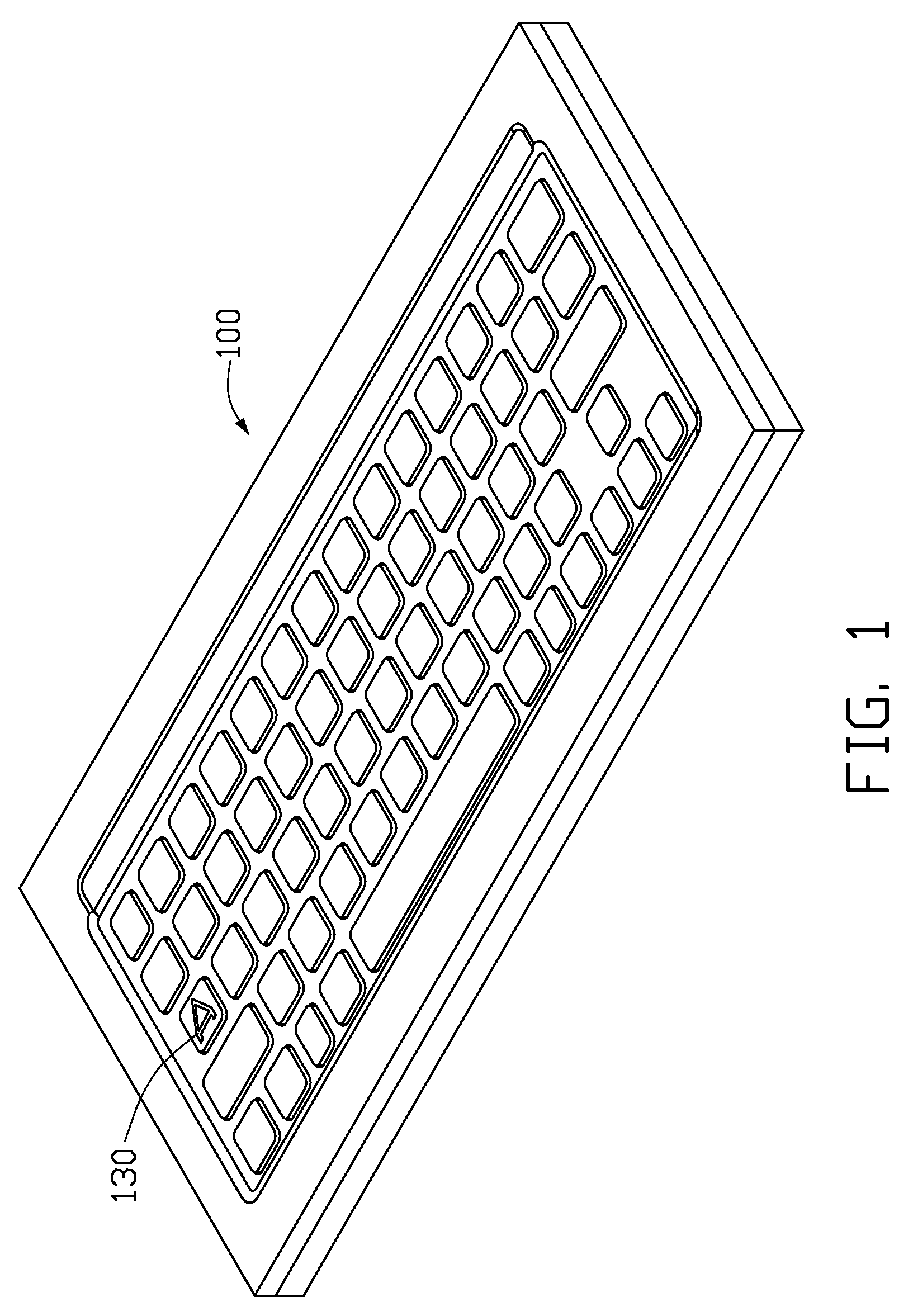
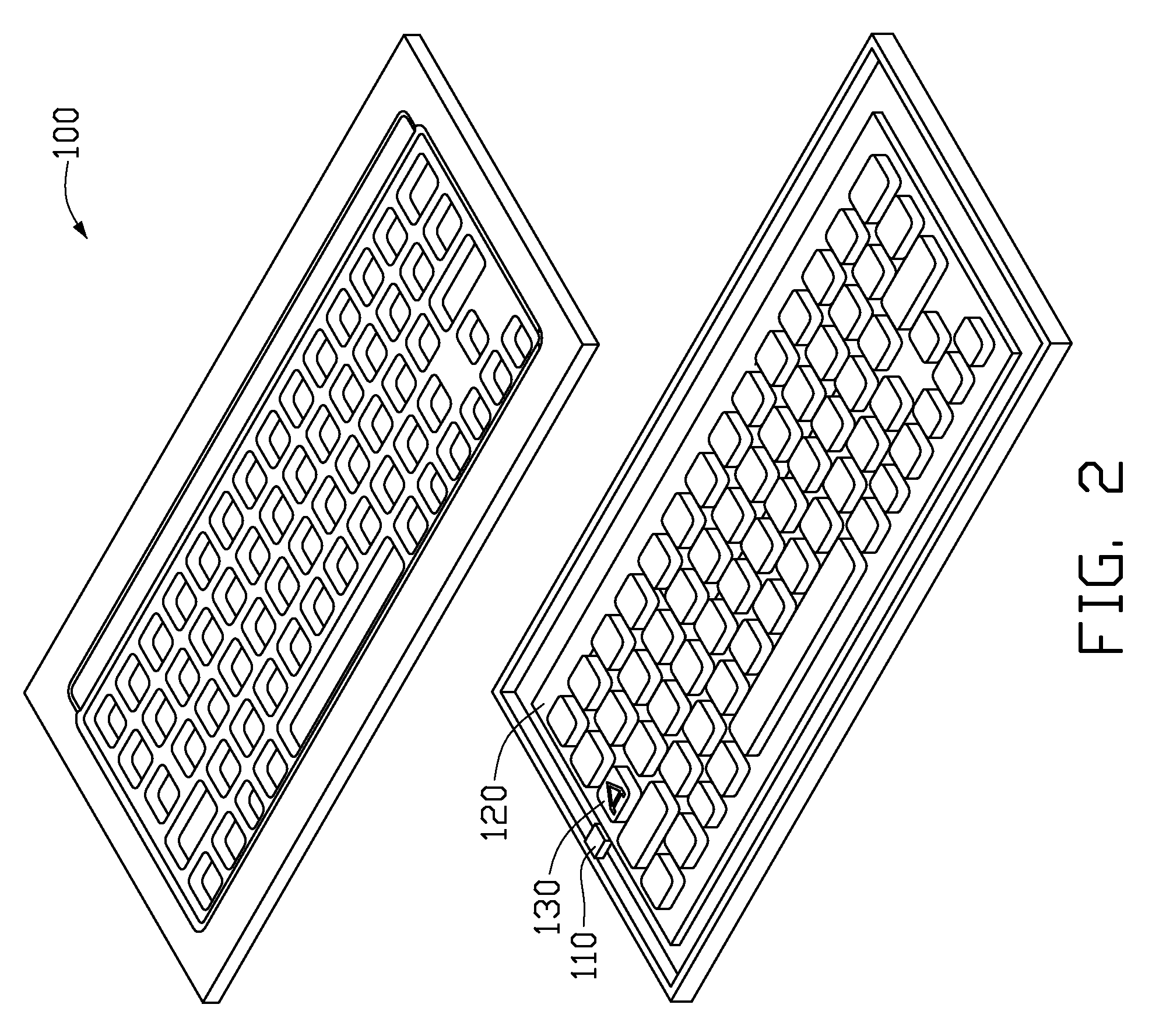
[0018]Referring to FIGS. 1 and 2, a luminous keyboard assembly 100, in accordance with a first embodiment, includes a light source 110 for emitting light, a light guide plate 120 adjacent to the light source 110 and a plurality of keys 130 mounted on the light guide plate 120. It should be understood that the luminous keyboard assembly 100 may further include a top shell (not labeled), a bottom shell (not labeled) and other components, which are well-known for one skilled in the art.

[0019]Referring to FIG. 3, the light guide plate 120 includes a light incident surface 121 facing the light source 110, a light emitting surface 122 located at a top thereof, a bottom surface 123 opposite to the light emitting surface 122, and several side surfaces 124. The light guide plate 120 receives light beams emitted from the light source 110, and evenly distributes the light beams over the entire light emitting surface 122 of the light guide plate 120 by reflection and diffusion. To improve the u...

second embodiment

[0033]When using the luminous keyboard assembly of the second embodiment, if a key 230 is pressed in response to manual manipulation, the light guiding cap 131 is pressed, and moves towards the light emitting surface 222 of the light guide plate 220 until the bottom surface 2312 of the light guiding cap 231 is attached to and optically coupled to the light emitting surface 222 of the light guide plate 220. Because the light guiding cap 231 is comprised of a light pervious material, the light beams will illuminate the key 230. When the key 230 is released, by the restoring force of the spring member 233, the light guiding cap 231 will move apart from the light emitting surface 222 of the light guide plate 220, then the key 230 restores and the brightness of the key 230 back to the same brightness with other keys.

[0034]Referring to FIGS. 8 and 9, in accordance with a third embodiment of the present invention, a key 330 of a luminous keyboard assembly (not shown) is shown. The differen...


PUM


Abstract

An exemplary keyboard assembly includes a light source for emitting light, a light guide plate and a plurality of keys mounted on the light guide plate. The light guide plate includes a light incident surface facing the light source and a light emitting surface. Each key includes a cap, a light guide portion coupled to the cap, and a spring member configured for biasing the light guide portion in a direction away from the light emitting surface of the light guide plate. Each key is movable relative to the light guide plate, in response to manual manipulation thereto, between a depressed position where the light guide portion is attached to and optically coupled to the light emitting surface of the light guide plate thereby illuminating the cap, and a rest position where the light guide portion is spaced apart from the light emitting surface of the light guide plate.

Description

BACKGROUND[0001]1. Technical Field[0002]The present invention relates to a keyboard assembly, and particularly to an luminous keyboard assembly.[0003]2. Discussion of Related Art[0004]With the rapid development of electronic technologies, electronic devices, such as computer, mobile telephones and personal digital assistants (PDAs), are now in widespread use. These electronic devices enable consumers to enjoy high technology services almost anytime and anywhere. A keyboard assembly as an input terminal has been an important member of an electronic device.[0005]A typical keyboard assembly does not have the function to illuminate itself, which makes it inconvenient to operate under dark conditions. At present, there are luminous keyboard assemblies which can illuminate themselves. A first kind of luminous keyboard assembly includes a keyboard module with a plurality of keys and a backlight module under the keyboard module. When the backlight module is turned on, the keyboard module il...

Claims


Application Information

Patent Timeline
Patent Type & Authority Patents(United States)
IPC IPC(8): H01H9/00
CPCH01H13/7006H01H13/83H01H2203/052H01H2205/002H01H2219/044H01H2219/06H01H2219/062H01H2231/002H01H2235/00
Inventor CHANG, JEN-TSORNG
Owner HON HAI PRECISION IND CO LTD
Why Eureka
Try Eureka