Optical path length sensor and method for optimal absorbance measurements

a path length sensor and optical path technology, applied in the field of fiber optic light delivery and collection systems, can solve the problems of difficult and/or time-consuming cleaning of cells or cuvettes for use with another sample, difficult and/or small sample quantities, and inability to accurately measure the absorbance of samples, etc., to achieve optimal signal-to-noise characteristics, optimal signal-to-noise characteristics, and rapid variation of sample absorbance

Active Publication Date: 2012-07-17
NANODROP TECH LLC
View PDF6 Cites 34 Cited by
  • Summary
  • Abstract
  • Description
  • Claims
  • Application Information

AI Technical Summary

Benefits of technology

[0019]b) prevent rotation of the circuit board and the second optical conduit with respect to the apparatus as a whole;thereby resulting in linear travel with minimal rotational effects and minimal change in optical alignment of second optical conduit with respect to the first optical conduit.

Problems solved by technology

Unfortunately, biological sampling techniques often yield very small quantities of material for analysis.
When dealing with very small sample volumes—for instance, from 1 to 2 microliters—it is difficult to create cells or cuvettes small enough to be filled and permit the industry standard 1 cm optical path to be used.
It is also difficult and / or time consuming to clean these cells or cuvettes for use with another sample.
Thus, conventional methods of photometry, spectrophotometry, fluorometry, spectrofluorometry, etc. are impractical when dealing with small sample volumes, such as of biological samples produced by laser-capture microdissection.
However, while anvils or pedestals are beneficial configurations, it is to be noted that such terminology does not express or imply any particular geometric form for the upper and lower members.
If the absorbance is too low, then so-called “shot” noise from the relatively high level of transmitted light may interfere with the measurement.
On the other hand, providing a sample with too great of an absorbance can cause the level of measured transmitted light to be too low, whereby electronic or other system background noise can preclude or obscure accurate determination of absorbance value.

Method used


Image

  • Optical path length sensor and method for optimal absorbance measurements
  • Optical path length sensor and method for optimal absorbance measurements
  • Optical path length sensor and method for optimal absorbance measurements

Examples


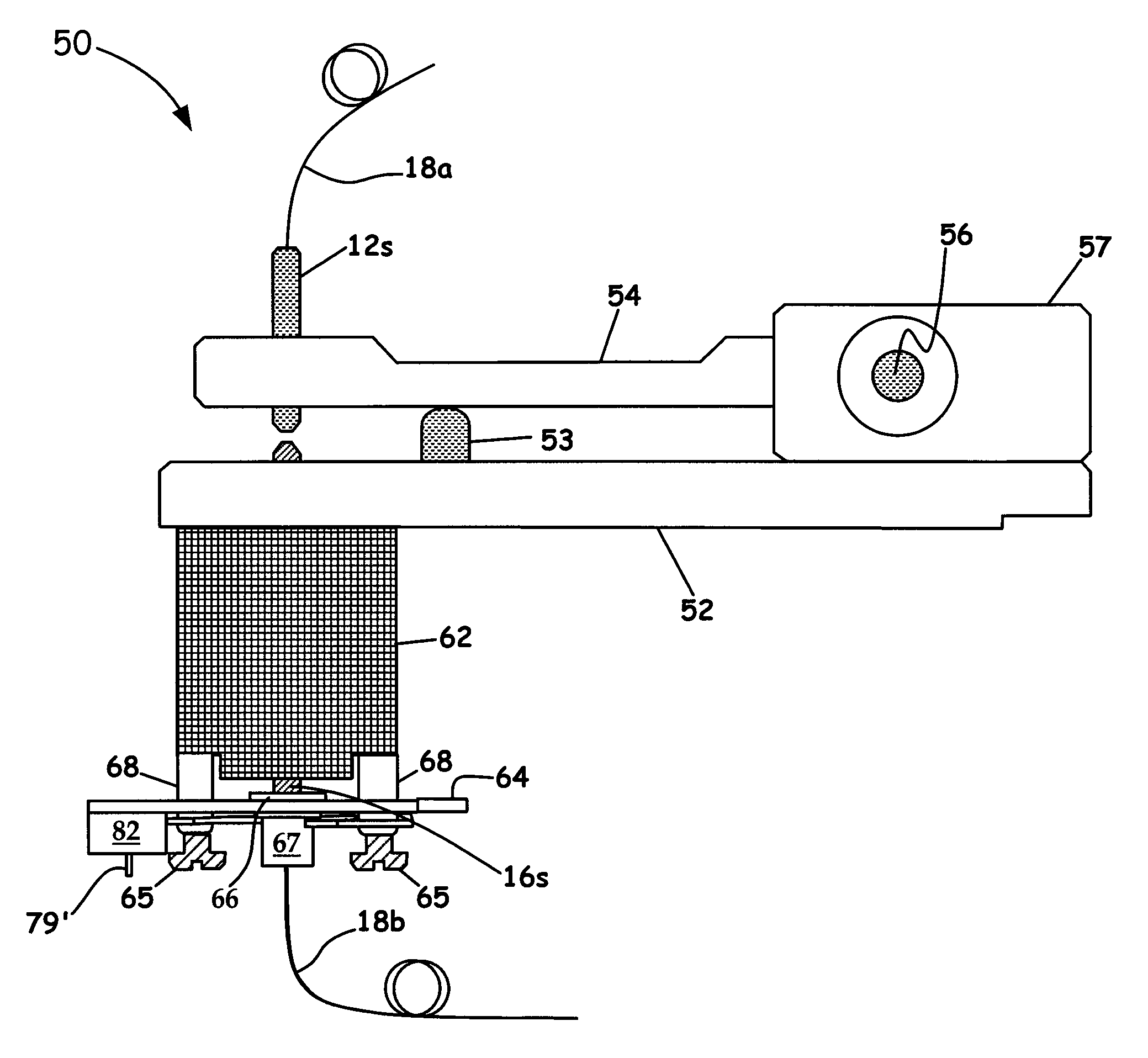
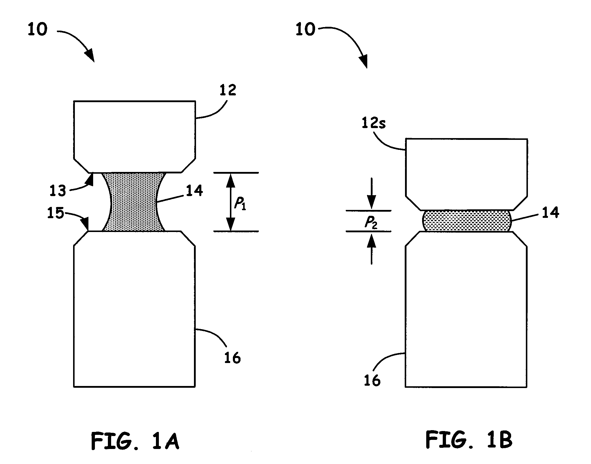
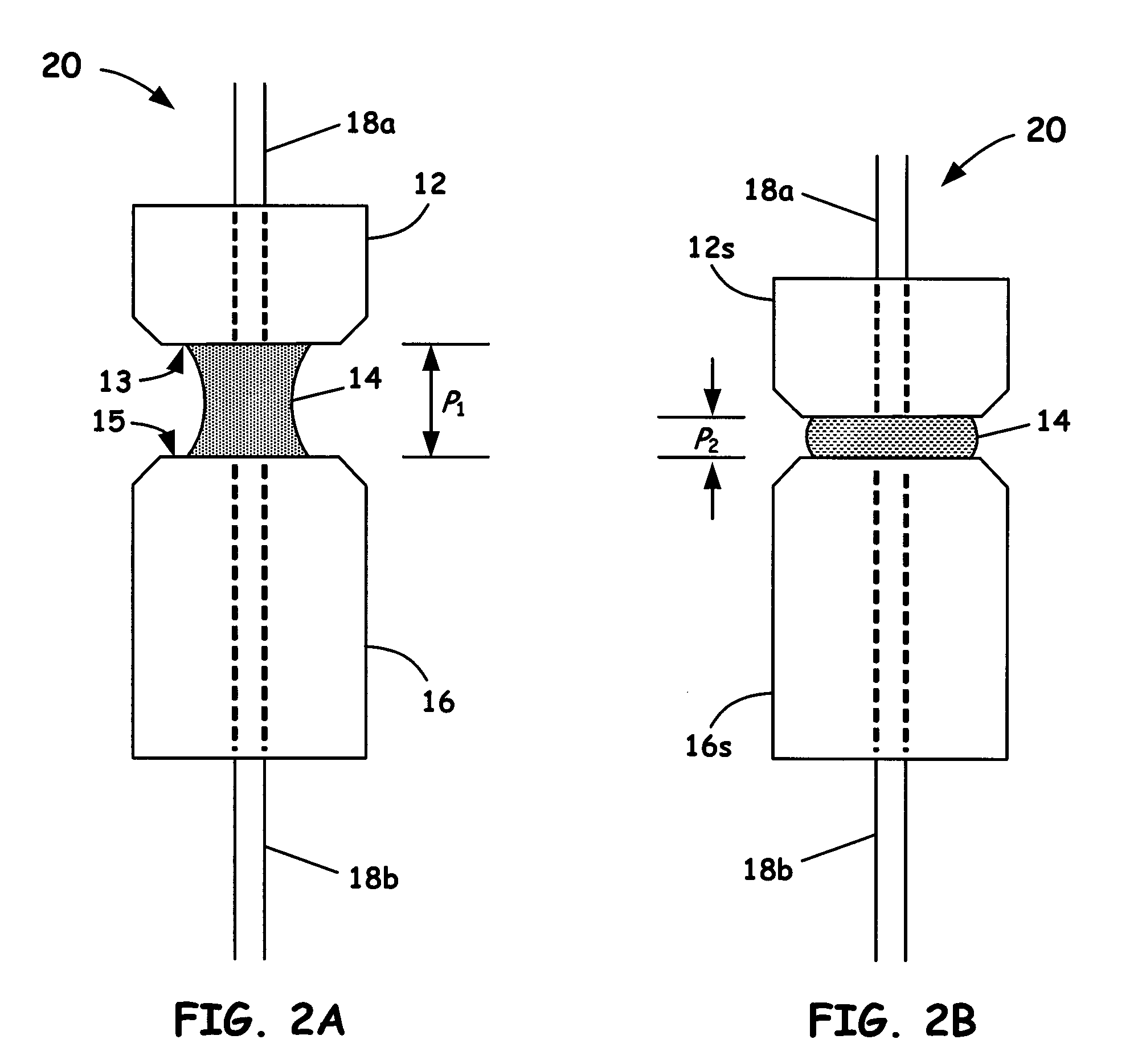
Embodiment Construction

[0041]In the description of the invention herein, it is understood that a word appearing in the singular encompasses its plural counterpart, and a word appearing in the plural encompasses its singular counterpart, unless implicitly or explicitly understood or stated otherwise. Furthermore, it is understood that for any given component or embodiment described herein, any of the possible candidates or alternatives listed for that component may generally be used individually or in combination with one another, unless implicitly or explicitly understood or stated otherwise. Additionally, it will be understood that any list of such candidates or alternatives is merely illustrative, not limiting, unless implicitly or explicitly understood or stated otherwise.

[0042]Moreover, unless otherwise indicated, numbers expressing quantities of ingredients, constituents, reaction conditions and so forth used in the specification and claims are to be understood as being modified by the term “about.” ...


PUM

PropertyMeasurementUnit
path lengthaaaaaaaaaa
wavelengthsaaaaaaaaaa
path lengthaaaaaaaaaa

Abstract

An apparatus is described in which an optical fiber is mounted within a fiber optic holder which includes the non-rotating shaft of a linear actuator. The fiber holder may be held captive in order to restrain the fiber holder and, consequently, the fiber mounted therein, from rotating during operation of the linear actuator, thereby resulting in linear travel with minimal rotational effects and minimal change in optical alignment of the fiber during travel. In addition, an optical path length sensor in conjunction with an optimized absorbance method of operation is utilized herein to provide micron precision of the displacement between respective receiving and transmission fibers so as to enable precise absorbance measurements from about 0.005 up to about 2.0 Absorbance Units for any given path length.

Description

RELATED APPLICATION[0001]This application claims the benefit of U.S. Provisional Application No. 61 / 102,740, entitled: “Optical Path Length Sensor for Measuring Absorbance,” and U.S. Provisional Application No. 61 / 102,553, entitled: “Method and Apparatus for a Linear Actuator and Fiber Optic Light Delivery and Collection System,” and U.S. Provisional Application No. 61 / 102,560, entitled: “Method for Optimum Optical Absorbance Measurements,” all of which were filed Oct. 3, 2008, and all of which are incorporated herein by this reference.FIELD OF THE INVENTION[0002]This invention relates to the field of spectrophotometers and related instruments for characterizing small-volume samples. More particularly, the invention relates to fiber optic light delivery and collection systems and a means for optimizing measurements within such instruments.BACKGROUND OF THE INVENTION[0003]Liquids, mixtures, solutions and reacting mixtures are often characterized using optical techniques such as photo...

Claims


Application Information

Patent Timeline
Patent Type & Authority Patents(United States)
IPC IPC(8): G01N21/00G01N1/10
CPCG01N21/0303G01N21/31G01N2021/036G01N2021/035
Inventor ROBERTSON, JR., CHARLES W.ASHMEAD, DAMIAN W.TOKASH, THOMAS A.
Owner NANODROP TECH LLC
Why Eureka
Try Eureka