
Moisture resistant microphone

a technology of microphones and coatings, applied in the direction of complete in-canal hearing aids, transducer details, electrical transducers, etc., can solve the problems of extended continuous wear and condensation, and achieve the effects of reducing condensation, ensuring microphone performance, and improving long-term reliability of hearing aids

Inactive Publication Date: 2007-01-04
INSOUND MEDICAL INC
View PDF10 Cites 58 Cited by
  • Summary
  • Abstract
  • Description
  • Claims
  • Application Information

AI Technical Summary

Benefits of technology

[0011] Various embodiments of the invention provide devices, assemblies and methods for improving the resistance of microphones such as condenser microphones to moisture and condensation. Many embodiments provide assemblies, devices and methods for improving the resistance of hearing aid microphones to moisture and condensation. Such hearing aid microphones can include those used in CIC hearing aids including CIC hearing aids configured to be worn in the bony portion of the ear canal for extended periods. Particular embodiments provide hydrophobic-coated microphone assemblies for improving the resistance of hearing aid microphones to moisture and condensation. Such embodiments can include hydrophobic-coated components for electret and other condenser based microphones.
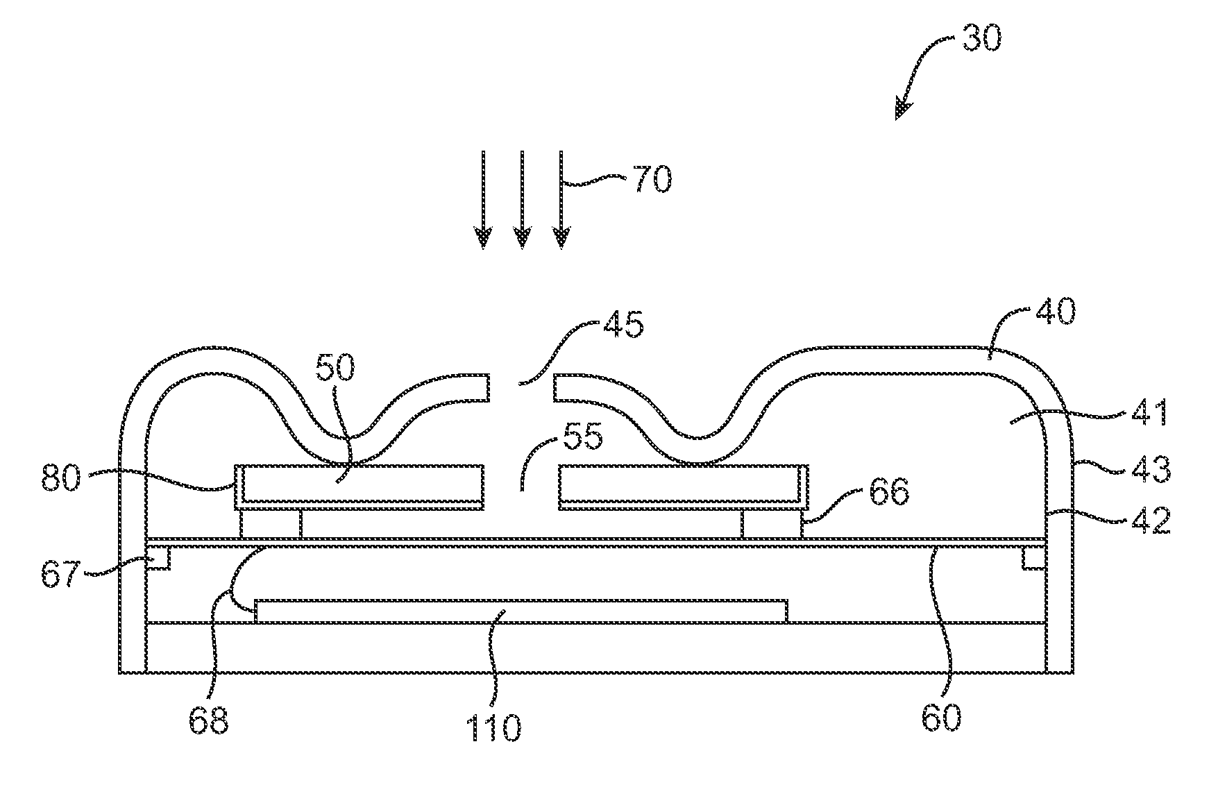
[0013] A hydrophobic coating can be applied to one or both of the backplate and the diaphragm surfaces so as to reduce wetting and / or water condensation on the backplate. This in turn, minimizes the neutralization of the electric field of the backplate surface from such condensation and thus preserves and stabilizes the electric field at the backplate surface. Typically, the coating will be applied to the backplate surface facing the diaphragm and versa visa. In one embodiment, the coating need only be applied to the backplate surface facing the diaphragm. Also, the thickness of the coating on either part is desirably configured to have minimal effect on the acoustical vibrations of the diaphragm as well as the electrical interactions of the diaphragm with the backplate. This in turn, minimizes any effects on acoustical parameters of the microphone such as microphone sensitivity, distortion level, bandwidth or like parameter, or the interaction of the backplate with the vibrating diaphragm. The coated membrane is thus acoustically operable through the range of audible sounds to provide an electrical signal usable by the hearing aid to provide an acoustical output that is a discernable representation of an audible sound inputted to the diaphragm. Desirably, the coating has a surface energy equal or less than that of the backplate surface. Also desirably, the thickness of the coating is small in relation to the offset distance e.g., less than 10%, and more preferably less than 5%. In preferred embodiments, the coating is a fluoropolymer, has a thickness of about 1 um and a surface energy (also described as surface tension) of about 11 to 12 dynes / cm but other materials with other properties are equally applicable. Also in preferred embodiments, the coating cures at room temperature and the coating solution is substantially free of pigments or other solids, which may absorb water or cause surface asperties. In a particular embodiment, the coating is a fluoropolymer and is applied to backplate having a fluoropolymer surface. The coating can also be applied throughout the interior and the exterior of the housing to not only reduce wetting and / or condensation on the backplate, but also prevent moisture from wicking into the housing through the sound port.
[0015] The coating can be configured to provide condensation protection to the microphone assembly for high humidity conditions within the ear canal including for relative humidities of 90% or greater at temperatures approximating body temperature. The coating can also be configured to not only reduce condensation in the humid environment of the ear canal, but do so when the wearer rapidly changes his ambient thermal environment such as coming from a cold outside environment to a heated indoors. Specific embodiments can be configured to provide condensation protection for sudden temperature changes of 10 or 20° C. or even greater. By reducing or preventing condensation, the coating serves to maintain a charge on the backplate surface and in turn maintain microphone performance in cases of rapid fluctuations in ambient temperature. The coating also improves long term reliability of the hearing aid by reducing or preventing the collection of liquid water within the microphone housing that may damage one or more electrical components of the hearing aid. This and related embodiments thus provide the wearer with an all-weather wear hearing aid allowing the wearer to freely move from one thermal environment to another without degradation in hearing aid performance both in the short term and in the long term. This all weather capability is particularly useful for extended wear hearing aids because the user need not remove the hearing aid in various thermal environments and the useful life of the hearing aid is extended allowing longer periods of wear.
[0016] Other embodiments of the invention provide methods for coating the microphone components such as the backplate and diaphragm with the hydrophobic coating. Such methods can include dip coating, spray coating and the like. Particular embodiments provide methods and coatings in which the coating can be cured at room temperature so as to minimize the potential for thermal damage to various components of the microphone including the diaphragm, backplate and various electrical components. Such embodiments provide a method of coating which reduces the probability of thermal failure of various microphone components. Further aspects and embodiments of the invention are described in the detailed description below.

Problems solved by technology

This can include periods of extended continuous wear when the hearing aid is worn in the bony portion of the ear canal.

Method used


Image

  • Moisture resistant microphone
  • Moisture resistant microphone
  • Moisture resistant microphone

Examples


Embodiment Construction

[0029] Various embodiments of the invention provide devices, assemblies and methods for improving the resistance of microphones such as condenser microphones to moisture and condensation. Many embodiments provide assemblies, devices and methods for improving the resistance of hearing aid microphones to moisture and condensation. Such hearing aid microphones can include those used in CIC hearing aids including those worn in the bony portion of the ear canal for extended periods and in varying environmental conditions. Particular embodiments provide hydrophobic-coated microphone assemblies for improving the resistance of hearing aid microphones to moisture and condensation including electret microphones.

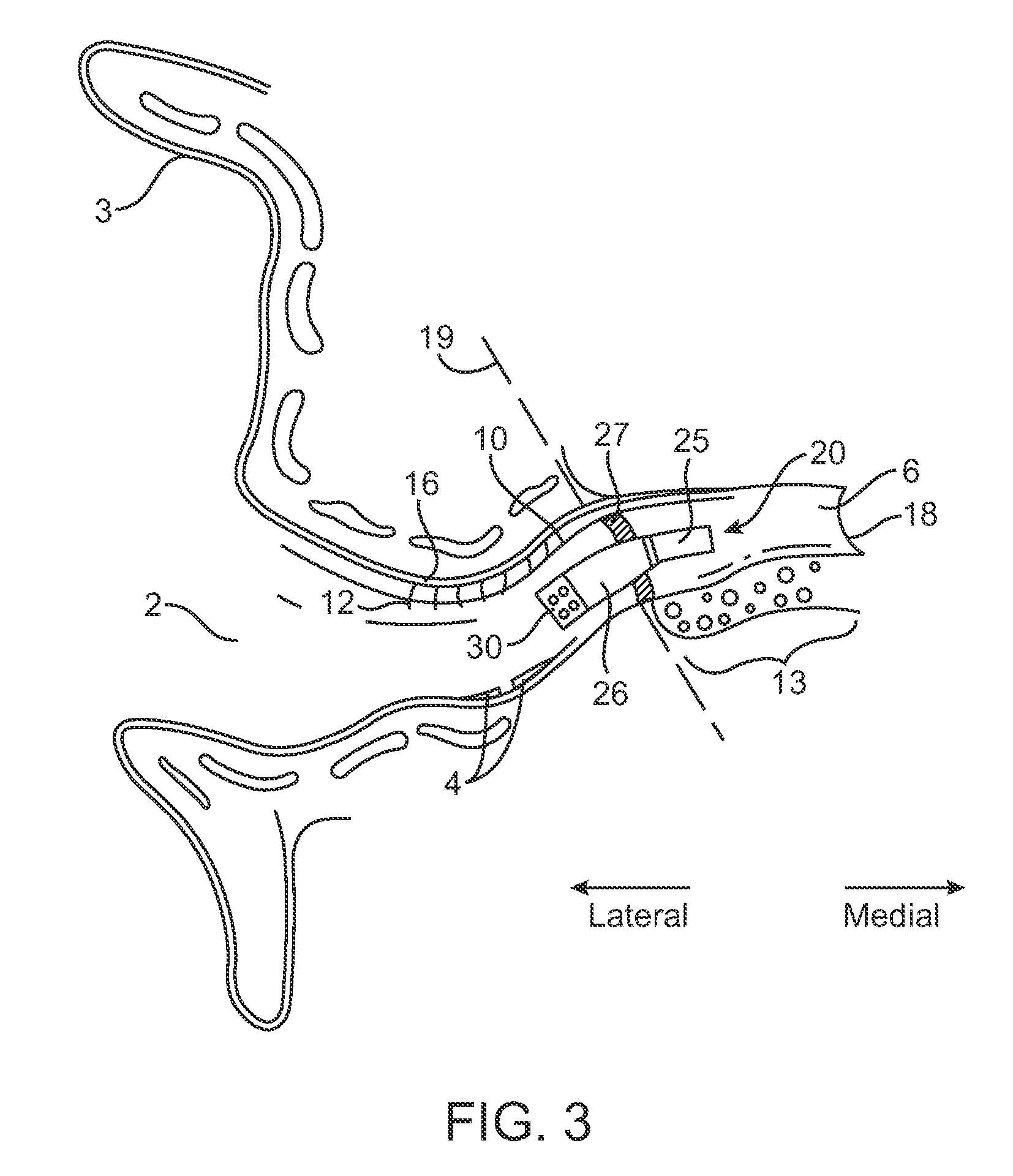
[0030] Referring now to FIG. 3, since many embodiments provide moisture resistant microphone assemblies that can be used in CIC hearing aids, an embodiment of a CIC hearing aid will now be described. Though it should be appreciated, that this is but one type of hearing aid that can ut...


PUM


Abstract

Embodiments of the invention provide microphone assemblies which are resistant to moisture. One embodiment provides a microphone assembly comprising a housing, a diaphragm disposed in the housing and a backplate disposed in the housing. The housing includes a sound inlet port for the entry of sound waves. The backplate includes a surface and an electret portion having an embedded permanent charge. The diaphragm is configured to vibrate in response to sound waves entering the housing. The vibrations of the diaphragm interact with the electret portion to produce an electrical signal associated with the sound waves entering the housing. A hydrophobic coating can be applied to one or both of the backplate and diaphragm surfaces so as to reduce condensation and / or wetting of the backplate. This minimizes neutralization of an electric field of the backplate surface from condensation preserving the field and the function of the microphone in humid environments.

Description

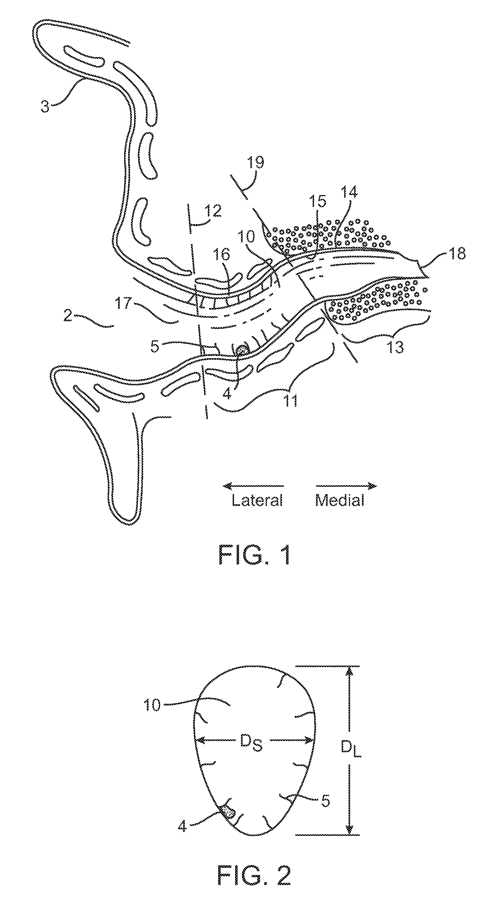
CROSS-REFERENCES TO RELATED APPLICATIONS [0001] This application claims the benefit of priority of U.S. Provisional Patent Application Ser. No.: 60 / 696265, entitled, Hearing Aid Microphone Protective Barrier filed on Jun. 30, 2005, the full disclosure of which is herein incorporated by reference.BACKGROUND OF THE INVENTION Field of the Invention [0002] Embodiments of invention relate to protective coatings for microphones. More specifically, embodiments of the invention relate to moisture protective coating for components used in microphones such as condenser microphones. Still more specifically, embodiments relate to moisture protective coating for microphone components used in hearing aids such as completely in the canal hearing aids. [0003] Since many hearing aid devices are adapted to be fit into the ear canal, a brief description of the anatomy of the ear canal will now be presented. While, the shape and structure, or morphology, of the ear canal can vary from person to person,...

Claims


Application Information

Patent Timeline
Patent Type & Authority Applications(United States)
IPC IPC(8): H04R25/00
CPCH04R1/086H04R19/016H04R25/602H04R2410/00H04R25/654H04R2225/023H04R25/652
Inventor RAM, SUNDERGABLE, RICHARDIPSEN, MICHAELDAY, IAN MICHAEL
Owner INSOUND MEDICAL INC
Learn More