Reduction in the acquisition duration of a phase-locked loop able to reconstitute a synchronisation signal transmitted over an IP network

a phase-locked loop and synchronisation signal technology, applied in the field of phase-locked loops able to reconstitute synchronisation signals transmitted over ip networks, can solve the problems of fluctuations in the length of time required for information, introduce strong jitter in the transmission of signals, etc., and achieve the effect of reducing the duration and shortening the acquisition phas

Inactive Publication Date: 2012-07-17
THOMSON LICENSING SA
View PDF16 Cites 0 Cited by
  • Summary
  • Abstract
  • Description
  • Claims
  • Application Information

AI Technical Summary

Benefits of technology

[0029]An advantage of the invention lies in its faculty to shorten considerably the duration of the acquisition phase and, as a result, to reduce the duration beyond which a piece of equipment comprising a reception device according to the invention is synchronised with a transmission device emitting samples on the network. The counting ramp CSR_PCR1 is generated with a count increment ΔC that is determined from a direct or indirect measure of a difference ERR between local samples PCR_loc1 and received samples PCRr.
lies in its faculty to shorten considerably the duration of the acquisition phase and, as a result, to reduce the duration beyond which a piece of equipment comprising a reception device according to the invention is synchronised with a transmission device emitting samples on the network. The counting ramp CSR_PCR1 is generated with a count increment ΔC that is determined from a direct or indirect measure of a difference ERR between local samples PCR_loc1 and received samples PCRr.

Problems solved by technology

A known disadvantage presented by an IP / Ethernet network is that it introduces a strong jitter in a transmission of signals, and particularly for the transmission of a synchronisation signal.
When such a signal is routed by an IP / Ethernet connection to different items of equipment for synchronising, this jitter results in fluctuations in the length of time required for the information carried by the synchronisation signal to reach the equipment.

Method used


Image

  • Reduction in the acquisition duration of a phase-locked loop able to reconstitute a synchronisation signal transmitted over an IP network
  • Reduction in the acquisition duration of a phase-locked loop able to reconstitute a synchronisation signal transmitted over an IP network
  • Reduction in the acquisition duration of a phase-locked loop able to reconstitute a synchronisation signal transmitted over an IP network

Examples


Embodiment Construction

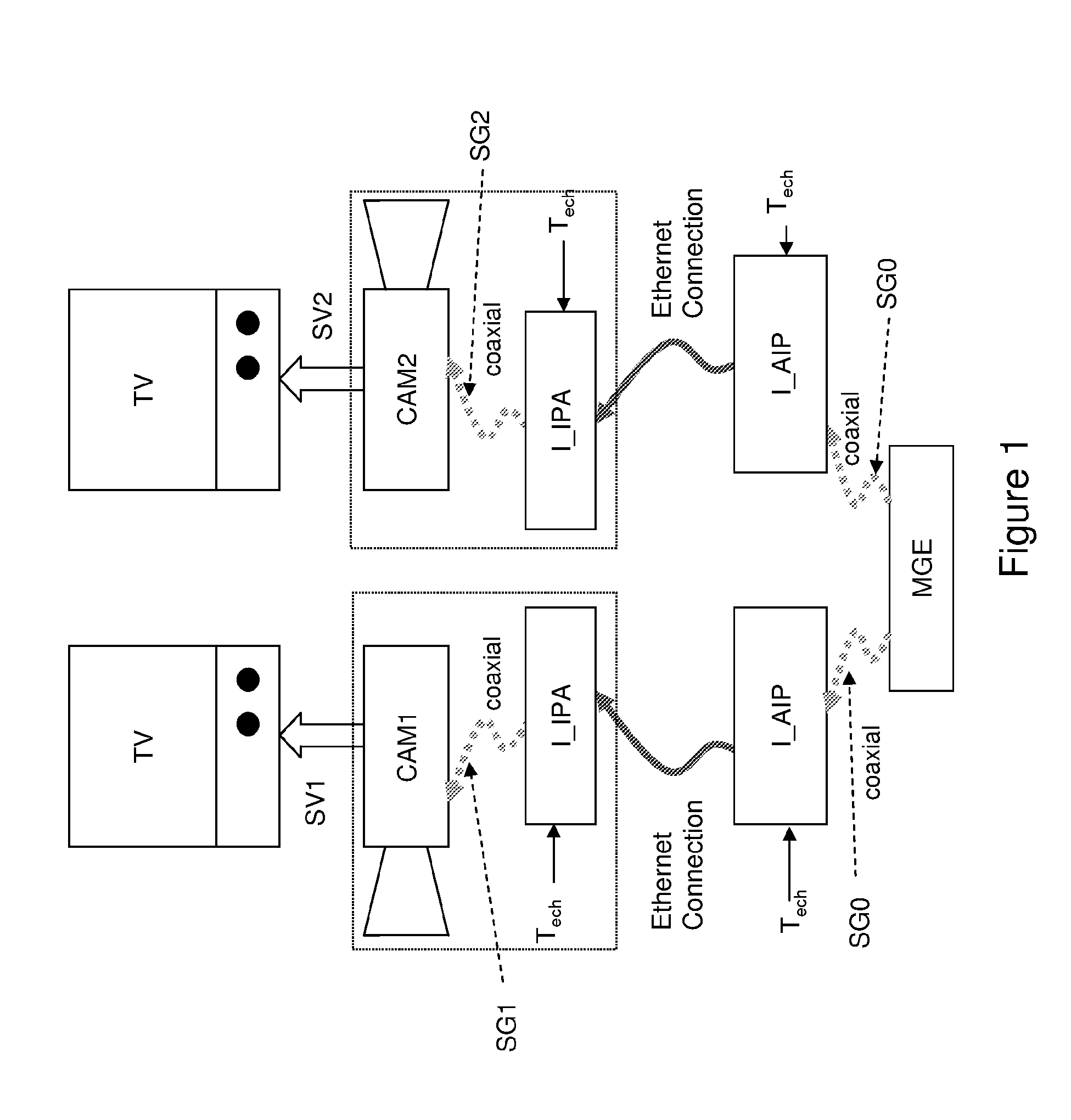
[0036]The current analogue domain is interfaced with the IP / Ethernet network on the transmission side, and the IP / Ethernet network is interfaced with the analogue domain on the reception side, as illustrated in FIG. 1.

[0037]In the same figure, the transmission side comprises a “Genlock master” MGE that is connected to an IP / Analogue interface IAIP. The Genlock master MGE sends a Genlock signal SG0 to the interfaces IAIP.

[0038]The reception side comprises two cameras (CAM1, CAM2) each connected to an IP / Analogue interface I_IPA. The interfaces I_IPA that will eventually be included in the cameras themselves are responsible for reconstructing the Genlock signals SG1, SG2 intended for cameras CAM1, CAM2. The cameras CAM1, CAM2 each produce a video signal SV1, SV2 that is required to be synchronised perfectly.

[0039]The transmission and reception sides are linked together by a packet switching network that is the source of a jitter occurring in the Genlock signal SG0.

[0040]A sampling pul...


PUM


Abstract

The present invention relates to the domain of video equipment. More specifically, it concerns a reception device that comprises the means for:receiving packets containing samples, that come from data sampled every Tech period, where Tech is from a time base synchronized on all the stations of said network,regenerating a counting ramp having a count increment and a range value PCR_Modulus, using a phase-locked loop PLL1 that receives the samples and that delivers local samples every Tech period and a reconstituted clock,initializing, at every zero-crossing of the counting ramp, an image counter that is determined by the reconstituted clock.According to the invention, it comprises, further, means for determining the values of count increments.

Description

SCOPE OF THE INVENTION[0001]This application claims the benefit, under 35 U.S.C. §365 of International Application PCT / EP2008 / 061757, filed Sep. 5, 2008, which was published in accordance with PCT Article 21(2) on Mar. 12, 2009 in English and which claims the benefit of French patent application No. 07 / 57420, filed Sep. 7, 2007.[0002]The present invention relates to the domain of video equipment.[0003]The present invention relates more particularly to a device for the reception of a synchronisation signal on a packet switching network, for example of the IP type, whether the network is wired (for example Ethernet (IEEE802.3)) or wireless (for example IEEE 802.16 D-2004).PRIOR ART[0004]Progress in the ability of IP networks to transport all types of signal (data or video) has made it possible to use these networks as the “backbone” architecture for video studios. Of capital importance to this evolution is therefore having a single infrastructure for the transport of data. Whereas in ...

Claims


Application Information

Patent Timeline
Patent Type & Authority Patents(United States)
IPC IPC(8): H04J3/06
CPCH03L7/10H03L7/101
Inventor TAPIE, THIERRYDEFRANCE, SERGEMACE, GAEL
Owner THOMSON LICENSING SA
Why Eureka
Try Eureka