Device for reducing rattling noises in variable-speed transmissions

a technology of variable-speed transmission and rattling noise, which is applied in the direction of gearing details, gearing, hoisting equipment, etc., can solve the problems of uncompletely prevented radial mobility of the rattling noise, and achieve the effects of reducing rattling noise, reducing rattling noise, and reducing rattling nois

Inactive Publication Date: 2012-07-24
ZF FRIEDRICHSHAFEN AG
View PDF14 Cites 4 Cited by
  • Summary
  • Abstract
  • Description
  • Claims
  • Application Information

AI Technical Summary

Benefits of technology

[0011]In both of the embodiments described, movements and vibrations of the loose gearwheels in the radial direction are damped or prevented by mechanically bracing the spring element, so that the loose wheels that are not involved in the force flow at least no longer impact so strongly against the adjacent elements and the noise produced thereby is substantially reduced. Despite this, the radial play required for load equalization as described earlier is still present.
[0015]Mounting of the roller bearing can also be realized with a roller bearing race in such manner that no axial forces are transferred. For this, for example a roller bearing race can be used which has only one bearing ring, this bearing ring being arranged on the main shaft and the rolling bodies of the roller bearing rolling directly on the surface of the central bore of the loose gearwheel. Thus, the loose wheel is not axially fixed relative to the rolling bodies and therefore also relative to the main shaft. In this way the axial bracing force of the spring element is left free and uninfluenced by other axial forces.
[0016]According to a further preferred design the loose gearwheel is supported in the axial direction between two buffer disks that are axially fixed on the main shaft. In this way, for example axial forces produced by operation of oblique-toothed spur gears or when the associated gear is engaged, are transferred directly via the buffer disks to the main shaft, without influencing the axial bracing force of the spring element on the roller bearing. Particularly in combination with the above-described, axial-force-free mounting on the roller bearing can be utilized. With a constant, calculable and preadjustable axial bracing force, constant damping of the movements in the radial direction can be ensured.
[0021]The present invention also includes a variable-speed transmission with a device for reducing rattling noise.
[0022]Finally, according to a preferred embodiment a variable-speed transmission is claimed, in which the device for reducing rattling noise is provided only for the reverse gear. Surprisingly, it has been found that this measure substantially reduces rattling noise in all the gears. That is attributed to the fact that the rattling noise in all the gears is mainly caused by vibrations in the reverse gear Thanks to the reduction of vibrations, according to the invention, of the loose gearwheels and thus of the rattling noise in the reverse gear, the rattling noise of the entire transmission is reduced because due to the reduction of vibration in the reverse gear, the forward gears too tend to rattle considerably less. Thus, with little design and structural complexity a reduction of annoying rattling noise throughout the transmission can be achieved.

Problems solved by technology

Thus, the roller bearing is axially fixed on the main shaft by the spring element, but its radial mobility is not completely prevented.

Method used


Image

  • Device for reducing rattling noises in variable-speed transmissions
  • Device for reducing rattling noises in variable-speed transmissions
  • Device for reducing rattling noises in variable-speed transmissions

Examples


Embodiment Construction

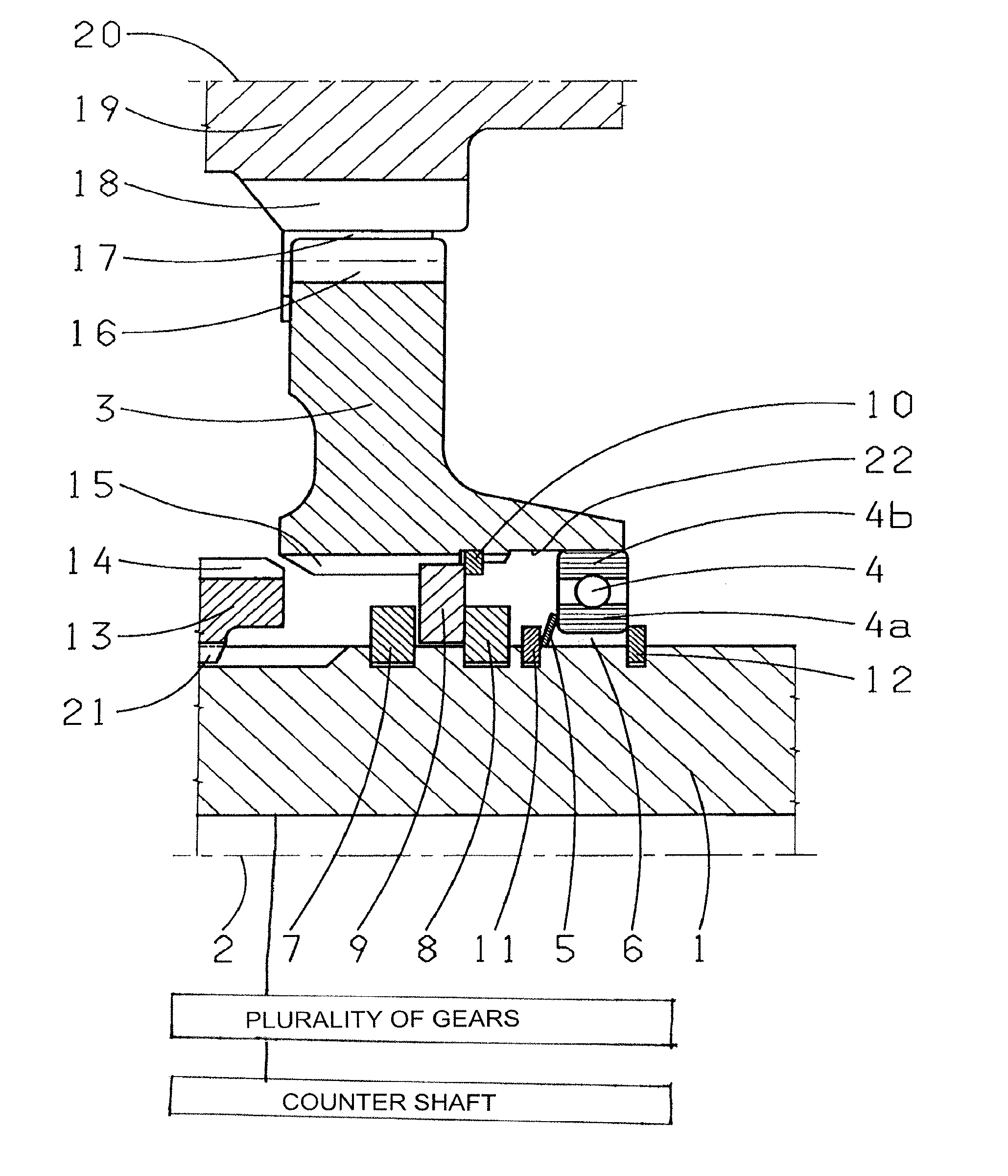
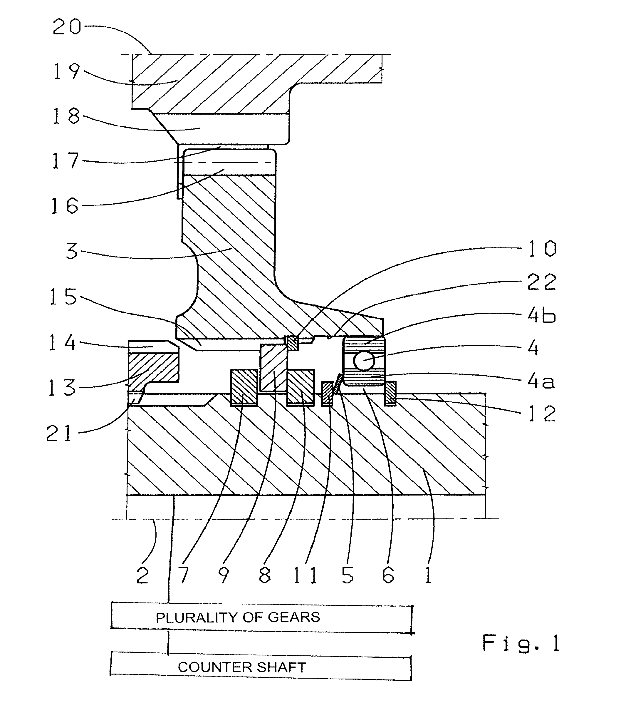
[0027]The embodiment shown in FIG. 1 comprises a loose gearwheel 3 for the reverse gear, which is fitted to rotate around the main shaft 1 and its central axis 2. In the load-free condition, i.e. when the reverse gear is not engaged, the loose gearwheel 3 is driven by the countershaft 19 via an intermediate gear 17. The intermediate gear 17 brings about the reversal of rotation direction that is required for the reverse gear. For this purpose the teeth 18 of the countershaft mesh with spur teeth of the intermediate gear 17. In turn, the spur teeth of the intermediate gear 17 engage with the spur teeth 16 of the loose gearwheel 3. In the representation shown, the intermediate gear 17 is outside the plane of the drawing and is largely hidden from view by the teeth 18 of the countershaft and those of the loose gearwheel 3.

[0028]To engage the reverse gear, the loose gearwheel 3 is connected in a rotationally fixed manner to the main shaft 1 by moving the shift sleeve 13 in the direction...


PUM


Abstract

A device for reducing rattling noises in a variable-speed transmission having a main shaft, two countershafts and gearwheels that are mounted, with some radial play relative to the main shaft, for rotation around the main shaft. To engage a gear, a respective loose gearwheel can be connected in a rotationally fixed manner to the main shaft. In a first embodiment, at least one loose gearwheel is mounted on the main shaft by at least one roller bearing, and the roller bearing is axially fixed relative to the main shaft by at least one flexibly resilient element. In a second embodiment, the loose gearwheel is supported, by a roller bearing on a component that is fixed to the housing and has radial play. The roller bearing is axially fixed relative to the component fixed to the housing by at least one flexibly resilient element.

Description

[0001]This application claims priority from German patent application serial no. 10 2008 000 822.2 filed Mar. 26, 2008.FIELD OF INVENTION[0002]The present invention concerns a device for reducing rattling noises in variable-speed transmissions with two countershafts.BACKGROUND OF THE INVENTION[0003]Variable-speed transmissions with two countershafts and a central main shaft are known from the prior art. Main shaft gearwheels arranged to rotate on the main shaft are driven by the gearwheels on the countershafts. Only when operating in the associated gear are the main shaft gearwheels connected in a rotationally fixed manner to the main shaft. In other operating phases the main shaft gearwheels rotate loosely on the main shaft. Thus, the main shaft gearwheels are also called loose gearwheels.[0004]For the purpose of load equalization between the force flows through the two countershafts, in such transmissions the main shaft is mounted in as floating manner, i.e. with some radial play....

Claims


Application Information

Patent Timeline
Patent Type & Authority Patents(United States)
IPC IPC(8): F16H3/08
CPCF16H3/095Y10T74/19623F16H2057/127Y10T74/19233F16H57/0006
Inventor HEINZELMANN, KARL-FRITZ
Owner ZF FRIEDRICHSHAFEN AG
Why Eureka
Try Eureka