Pneumatic tire

a technology of pneumatic tires and blocks, applied in the field of pneumatic tires, can solve the problems of uneven wear, uneven wear, and uneven wear at the time of running on general road surfaces, and achieve the effects of maintaining the resistance to uneven wear and driving stability, not substantially deteriorating the stiffness of the block, and sufficient levels

Inactive Publication Date: 2012-07-24
THE YOKOHAMA RUBBER CO LTD
View PDF20 Cites 1 Cited by
  • Summary
  • Abstract
  • Description
  • Claims
  • Application Information

AI Technical Summary

Benefits of technology

[0005]The present invention has been made to solve the above-described problems of the conventional tires. An object of the present invention is to provide a pneumatic tire which has an improved performance of running on a muddy ground, and with which the resistance to uneven wear and the driving stability on general road surfaces are maintained respectively at sufficient levels.
[0007]According to the present invention, the land section on the outer side, in the tire width direction, of each circumferential groove is partitioned by the lateral grooves into the large number of blocks. Then, the cutout having the plurality of steps in the tire width direction is formed in the center region of the edge portion, facing the corresponding circumferential groove, of each of the blocks. Accordingly, since no cutout is formed in the front and rear sides, in the tire circumferential direction, of each block, the block stiffness is not substantially deteriorated. As a result, the stiffness thus maintained makes it possible to maintain the resistance to uneven wear and the driving stability at the time of running on general road surface respectively at sufficient levels.
[0008]Moreover, the kicking out muddy soil by the blocks each having a wide width, as well as the grasping of muddy soil by the cutouts improve the performance (particularly, the traction performance) at the time of running on a muddy ground.
[0009]Furthermore, since the improvement in the performance of running on a muddy ground eliminates the need for forming wider lateral grooves partitioning the land sections, this configuration is advantageous also in view of securing the resistance to uneven wear.

Problems solved by technology

However, since such a tire having a block pattern has a tread contact area smaller than that of a tire having a rib pattern, the following problem arises.
When the tire having a block pattern runs on general road surfaces, uneven wear called heel-and-toe wear is likely to occur in the surfaces of the blocks.
In particular, in a case where lateral grooves of a large width are formed in such a tire in order to secure the performance of running on a muddy ground, uneven wear becomes more likely to occur.
At the same time, since the block stiffness is reduced, the driving stability at the time of running on general road surfaces is deteriorated.
Since the block stiffness is reduced, the driving stability at the time of running on general road surfaces is deteriorated.
In addition, an insufficient width of each block leads to a deterioration in the performance (particularly, the traction performance) at the time of running on a muddy ground.

Method used


Image

  • Pneumatic tire
  • Pneumatic tire
  • Pneumatic tire

Examples


examples

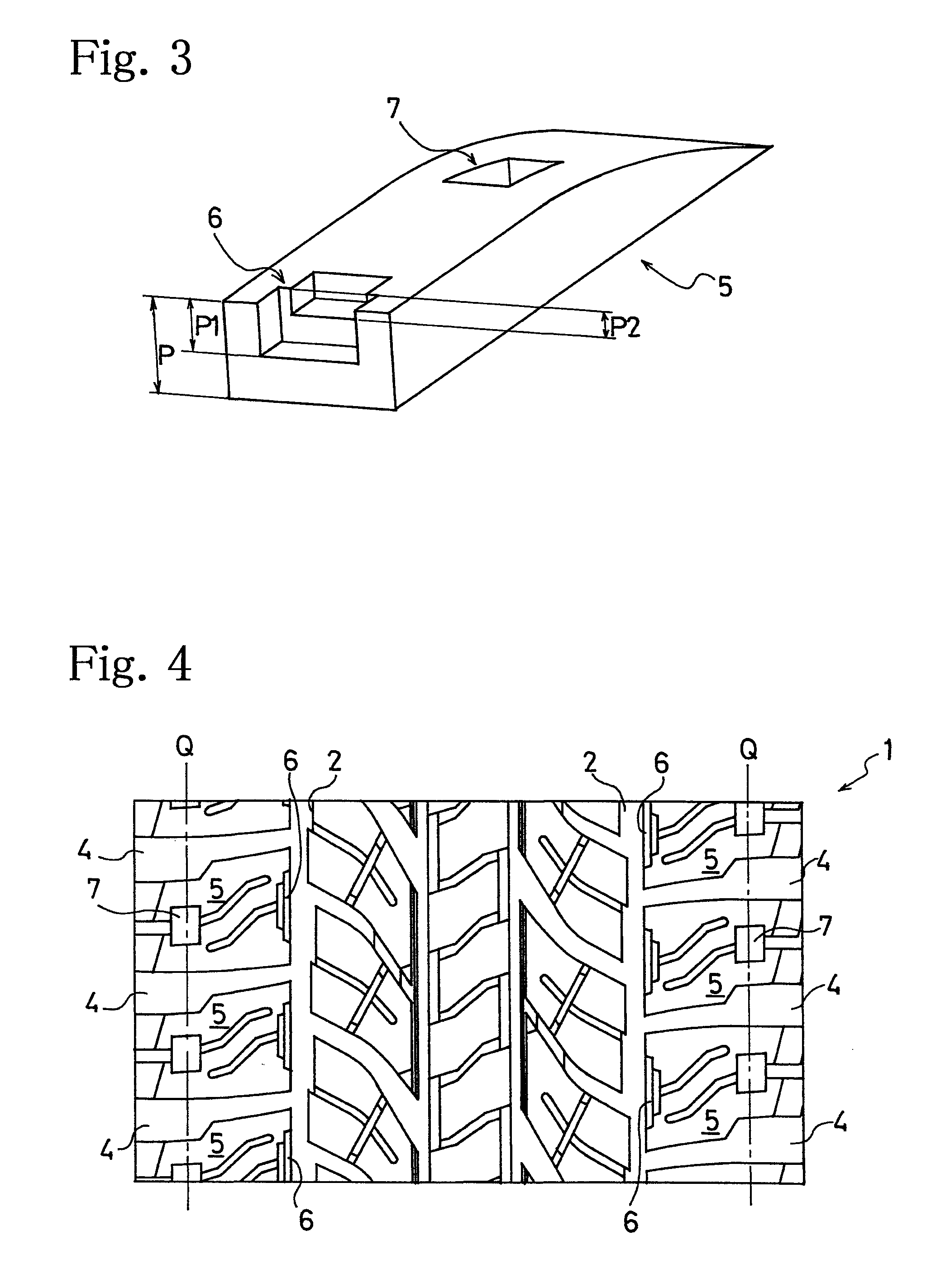
[0030]A conventional pneumatic tire (Conventional Example), pneumatic tires of the present invention (Examples 1 to 7), and a pneumatic tire for comparison (Comparative Example) were prepared. Each of these tires had a tire size of 265 / 70R16 112, and a tread pattern shown in FIG. 4 although the cutouts 6 were not formed in the conventional tire. Concurrently, each of these tires was provided with the second cutouts 7 of one step formed therein. Here, each of the second cutouts 7 had a depth of 3.3 mm, a length of 10 mm in the circumferential direction, and a length of 3 mm in the width direction. Moreover, the tires of Examples 1 to 7 and Comparative Example were provided with different specifications of the cutouts 6 from one another as shown in Table 1.

[0031]Each of these tires was mounted onto a rim having a rim size of 16×7JJ, inflated to an air pressure of 200 kPa, and then mounted on a domestically-produced four-wheel drive vehicle (the engine displacement: 2500 cc). Each of t...


PUM


Abstract

Provided is a pneumatic tire having a tread surface (1) with a tread pattern having: at least two circumferential grooves (2) extending in the tire circumferential direction to define land sections (3) on the outer sides in the tire width direction; and lateral grooves (4) extending in the tire width direction to partition the land sections (3) into a large number of blocks (5). In addition, in each of the blocks (5), a cutout (6) is formed in the center region of an edge portion of the block (5), the edge facing the corresponding circumferential groove (2). The cutout (6) has plural steps in the tire width direction. This structure improves the performance of running on a muddy ground with the resistance to uneven wear and the driving stability on general road surfaces maintained respectively at sufficient levels.

Description

[0001]This application is a national phase under 35 U.S.C. §371, of PCT International Application No. PCT / JP2006 / 322631, filed Nov. 14, 2006.TECHNICAL FIELD[0002]The present invention relates to a pneumatic tire. More specifically, the present invention relates to a pneumatic tire which has an improved performance of running on a muddy ground, and with which the resistance to uneven wear and the driving stability on general road surfaces are maintained respectively at sufficient levels.BACKGROUND ART[0003]Conventional tires to be mounted on four-wheel drive vehicles and light trucks need to be excellent in off-road running performance. In order to secure the off-road running performance, these tires employ a tread pattern formed primarily of a block pattern with a large number of edge portions. However, since such a tire having a block pattern has a tread contact area smaller than that of a tire having a rib pattern, the following problem arises. When the tire having a block pattern...

Claims


Application Information

Patent Timeline
Patent Type & Authority Patents(United States)
IPC IPC(8): B60C11/11
CPCB60C11/0302B60C11/032B60C11/13B60C11/1376B60C2011/133Y10S152/902
Inventor KOJIMA, HIROYUKI
Owner THE YOKOHAMA RUBBER CO LTD
Why Eureka
Try Eureka