Spin resistant threaded insert
a threaded insert and thread technology, applied in the direction of screws, dowels, fastening means, etc., can solve the problems of substantial increase in spin out values and filling the void between the knurls
- Summary
- Abstract
- Description
- Claims
- Application Information
AI Technical Summary
Benefits of technology
Problems solved by technology
Method used
Image
Examples
Embodiment Construction
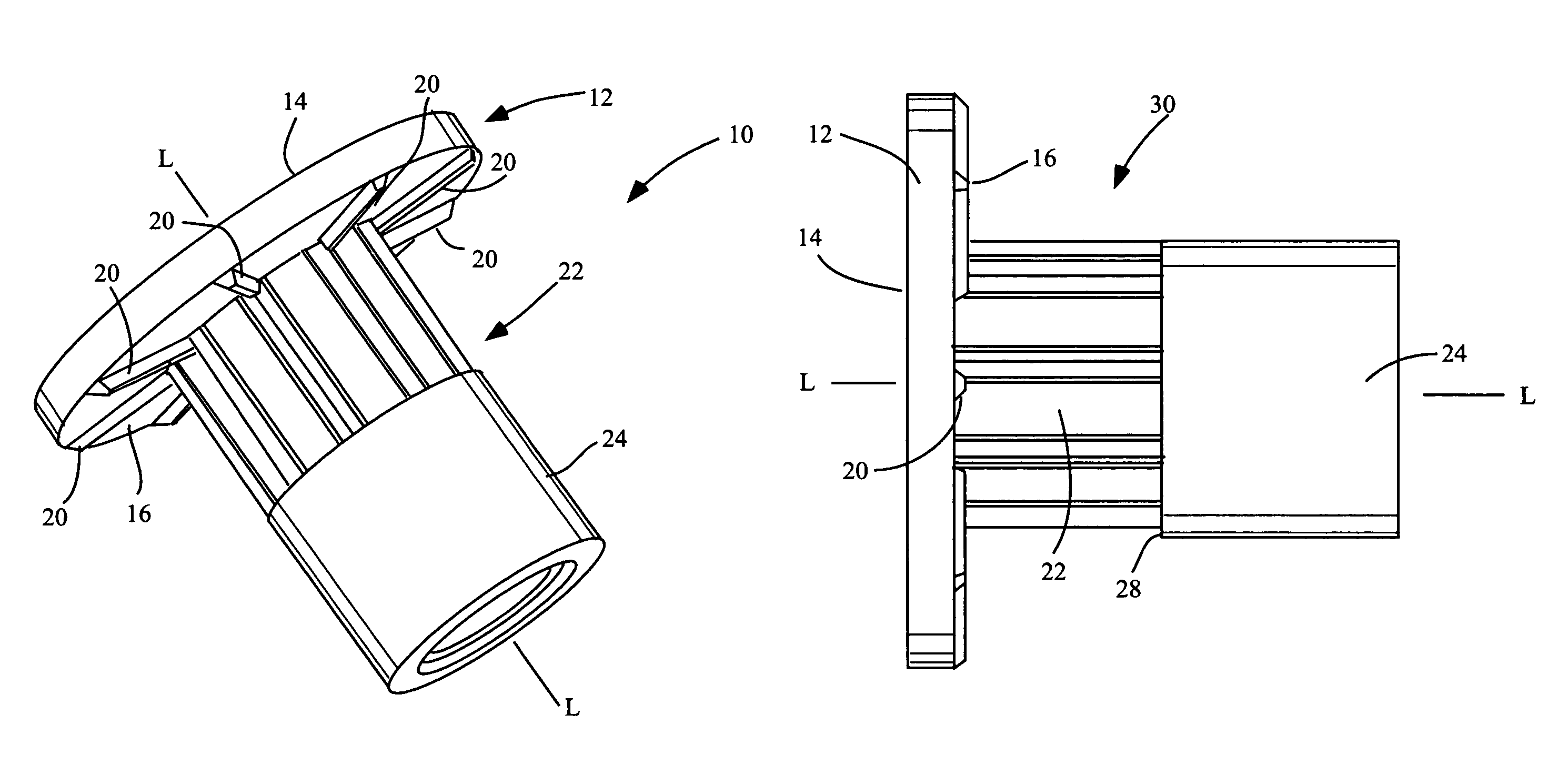
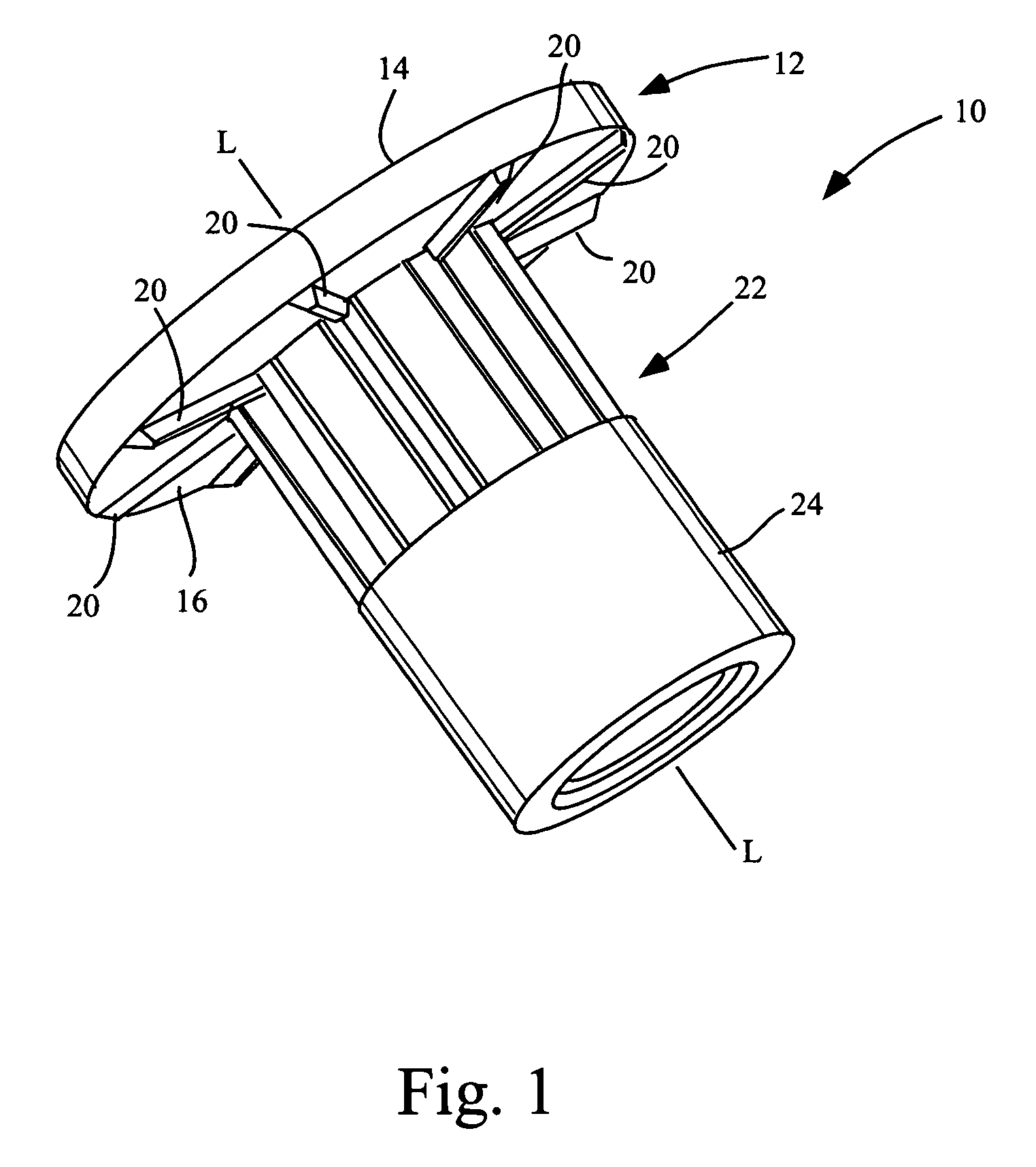
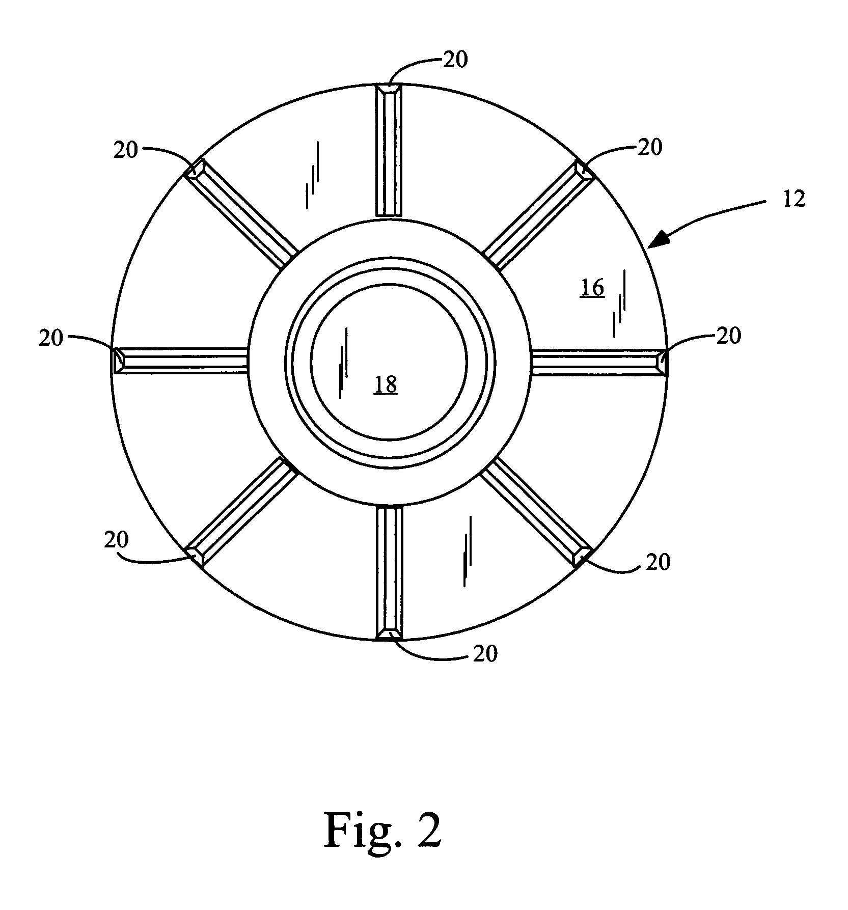
[0014]Referring now to the figures, FIG. 1 shows an embodiment of the disclosed threaded insert 10. Insert 10 comprises circular head member 12. Circular head member 12 comprises a top side 14 and an underside 16. Head member 12 comprises a circular opening 18 which has a center axis L which coincides with the center axis of the circular head member, such that the circular opening 18 is centrally located within head member 12. Circular opening 18 may extend through the entire length of the threaded insert 10, although another embodiment might include a closed end. The underside 16 of head member 12 comprises a plurality of knurls 20 which radiate outwardly on the underside 16 of circular head member 12. As shown in FIG. 1, the knurls may comprise a polygonal profile.
[0015]Insert 10 comprises a hollow body having a first section 22 and an axially adjacent second section 24. First section 22 comprises a proximal end 26, which transitions into head member 12. First section 22 further c...
PUM
 Abstract
Description
Claims
Application Information
 - R&D
- Intellectual Property
- Life Sciences
- Materials
- Tech Scout
- Unparalleled Data Quality
- Higher Quality Content
- 60% Fewer Hallucinations
Browse by: Latest US Patents, China's latest patents, Technical Efficacy Thesaurus, Application Domain, Technology Topic, Popular Technical Reports.
© 2025 PatSnap. All rights reserved.Legal|Privacy policy|Modern Slavery Act Transparency Statement|Sitemap|About US| Contact US: help@patsnap.com


