Spin resistant threaded insert

a threaded insert and thread technology, applied in the direction of screws, dowels, fastening means, etc., can solve the problems of substantial increase in spin out values and filling the void between the knurls

Active Publication Date: 2008-08-14
AVK INDAL PRODS
View PDF12 Cites 45 Cited by
  • Summary
  • Abstract
  • Description
  • Claims
  • Application Information

AI Technical Summary

Benefits of technology

[0009]The threaded insert further comprises a hollow body, comprising a first section and an axially adjacent second section, the first section comprising a proximal end attached to the first flange and a distal end at which point the first section integrally transitions into the second section. The first section comprises a pluralit

Problems solved by technology

During installation of the fastener the aggressive knurls on the outer diameter of the body in conjunction with knurls under the head

Method used


Image

  • Spin resistant threaded insert
  • Spin resistant threaded insert
  • Spin resistant threaded insert

Examples


Embodiment Construction

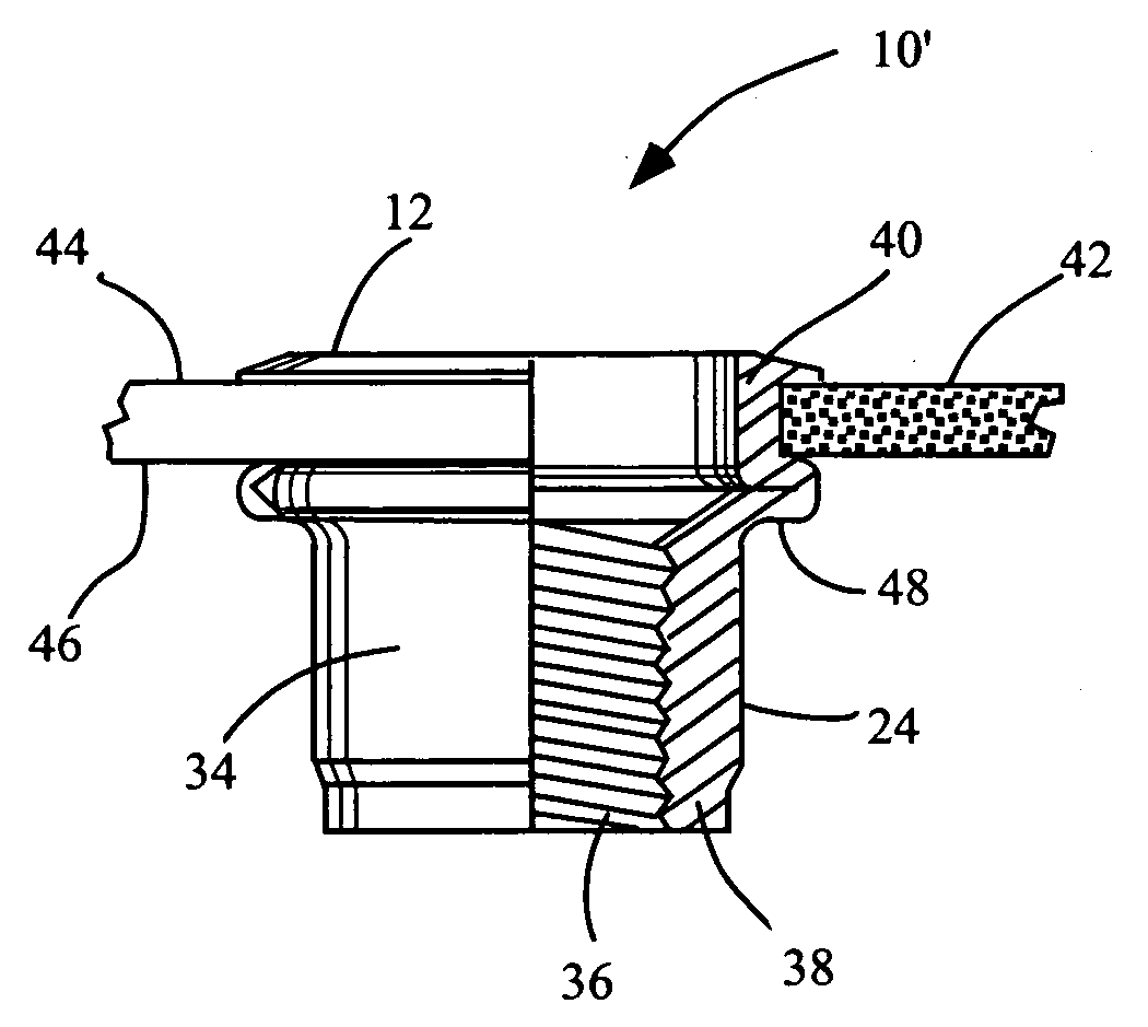
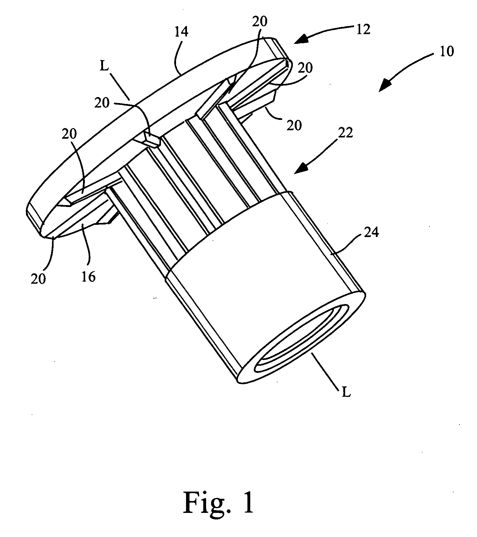
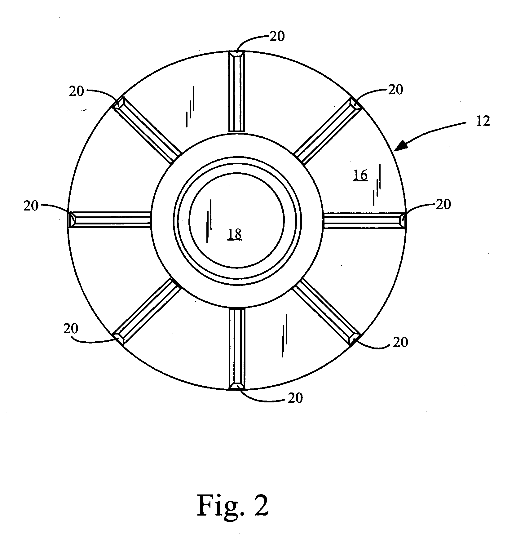
[0015]Referring now to the figures, FIG. 1 shows an embodiment of the disclosed threaded insert 10. Insert 10 comprises circular head member 12. Circular head member 12 comprises a top side 14 and an underside 16. Head member 12 comprises a circular opening 18 which has a center axis L which coincides with the center axis of the circular head member, such that the circular opening 18 is centrally located within head member 12. Circular opening 18 may extend through the entire length of the threaded insert 10, although another embodiment might include a closed end. The underside 16 of head member 12 comprises a plurality of knurls 20 which radiate outwardly on the underside 16 of circular head member 12. As shown in FIG. 1, the knurls may comprise a polygonal profile.

[0016]Insert 10 comprises a hollow body having a first section 22 and an axially adjacent second section 24. First section 22 comprises a proximal end 26, which transitions into head member 12. First section 22 further c...


PUM


Abstract

A threaded collapsible insert is utilized for insertion into a hole in a workpiece for subsequent installation of a threaded fastener. The insert has a axially-aligned opening extending for most or all of the entire length of the body of the insert. The hollow body has a first section and a second section, where the wall thickness of the first section is less than the wall thickness of the second section, such that the first section preferentially collapses upon application of a linear force to the insert. The second section comprises internal threads for engaging the fastener. The head member has a top side and an underside. The underside of the head member may comprise a plurality of knurls radiating outwardly on the underside of the flange. The outside of the first section may also comprise a plurality of axially aligned rib members extending from the proximal end to the distal end.

Description

CROSS-REFERENCE TO RELATED APPLICATION[0001]U.S. Provisional Application No. 60 / 901,806 for this invention was filed on Feb. 14, 2007, for which application this inventor claims domestic priority.BACKGROUND OF THE INVENTION[0002]The present invention relates to an apparatus for attaching threaded fasteners to a workpiece, which usually will have a first side, for which access is available, and a second side, which may be a blind side where access is not available. More particularly, this invention relates to a threaded insert having structural features which increase the resistance of the insert from spinning within the workpiece.[0003]It is known to use threaded rivet nuts or threaded inserts as anchors for threaded fasteners in a number of different applications, including thin wall applications, such as sheet materials fabricated from metals, plastics and composites, which may be too thin to be tapped with threads.[0004]In many cases, there is access only to one side of the workp...

Claims


Application Information

Patent Timeline
IPC IPC(8): F16B37/00
CPCF16B37/067F16B33/002
Inventor NERI, FRANK
Owner AVK INDAL PRODS
Why Eureka
Try Eureka