Check patentability & draft patents in minutes with Patsnap Eureka AI!

Battery module having cooling means, and middle or large-sized battery pack containing the same

a battery module and cooling means technology, applied in the field of batteries, can solve the problems of battery module catching fire or explosion, large amount of heat generated by high-power, and accelerated deterioration of battery modules, so as to reduce temperature deviation, increase cooling rate, and reduce heat dissipation

Active Publication Date: 2012-07-24
LG ENERGY SOLUTION LTD
View PDF10 Cites 3 Cited by
  • Summary
  • Abstract
  • Description
  • Claims
  • Application Information

AI Technical Summary

Benefits of technology

[0012]It is an object of the present invention to provide a battery module constructed to have a structure in which a plurality of sequentially stacked battery cells are covered by bendable heat dissipation members such that heat transfer is achieved by conduction, thereby uniformly maintaining the overall temperature of the battery module and reducing temperature deviation.
[0038]The battery modules may be spaced apart from each other by a predetermined gap serving as a coolant channel for allowing a coolant to flow therethrough. Even in this structure, it may be possible to considerably reduce the number of coolant channels as compared with middle- or large-sized battery packs using conventional cooling systems.

Problems solved by technology

Consequently, a large amount of heat is generated from the high-power, large-capacity secondary batteries during the charge and discharge of the batteries.
If the heat, generated from the battery module during the charge and discharge of the battery module, is not effectively removed, the heat accumulates in the battery module, with the result that the deterioration of the battery module is accelerated.
According to circumstances, the battery module may catch fire or explode.
In this structure, however, it is necessary to provide a plurality of coolant channels corresponding to the plurality of battery cells, with the result that the overall size of the battery module increases.
As a result, it may be complicated to design a cooling structure.
That is, the coolant channels having a width narrower than an inlet port of a coolant cause high pressure loss, with the result that there is great difficulty in designing the shape and position of inlet and outlet ports of the coolant.
As a result, there are design restrictions in, for example, power consumption, fan noise, and space.
Furthermore, battery cells located at the middle of the battery cell stack may not be satisfactorily cooled, and may deteriorate more rapidly than the outermost battery cells.
Such nonuniform deterioration of the battery cells may reduce service life of the battery module, which is not preferable in terms of safety.

Method used


Image

  • Battery module having cooling means, and middle or large-sized battery pack containing the same
  • Battery module having cooling means, and middle or large-sized battery pack containing the same
  • Battery module having cooling means, and middle or large-sized battery pack containing the same

Examples


Embodiment Construction

[0048]Now, exemplary embodiments of the present invention will be described in detail with reference to the accompanying drawings. It should be noted, however, that the scope of the present invention is not limited by the illustrated embodiments.

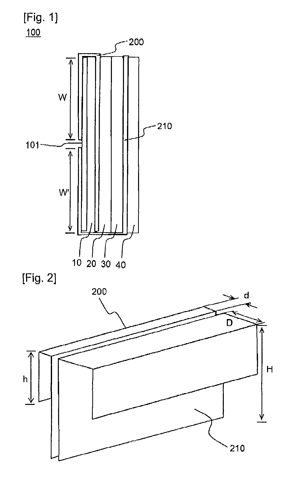
[0049]FIG. 1 is a partial front view typically illustrating a battery module according to an embodiment of the present invention. For convenience of description, battery cells are schematically shown while other members, such as electrode terminals and connection members, to constitute the battery module are omitted.

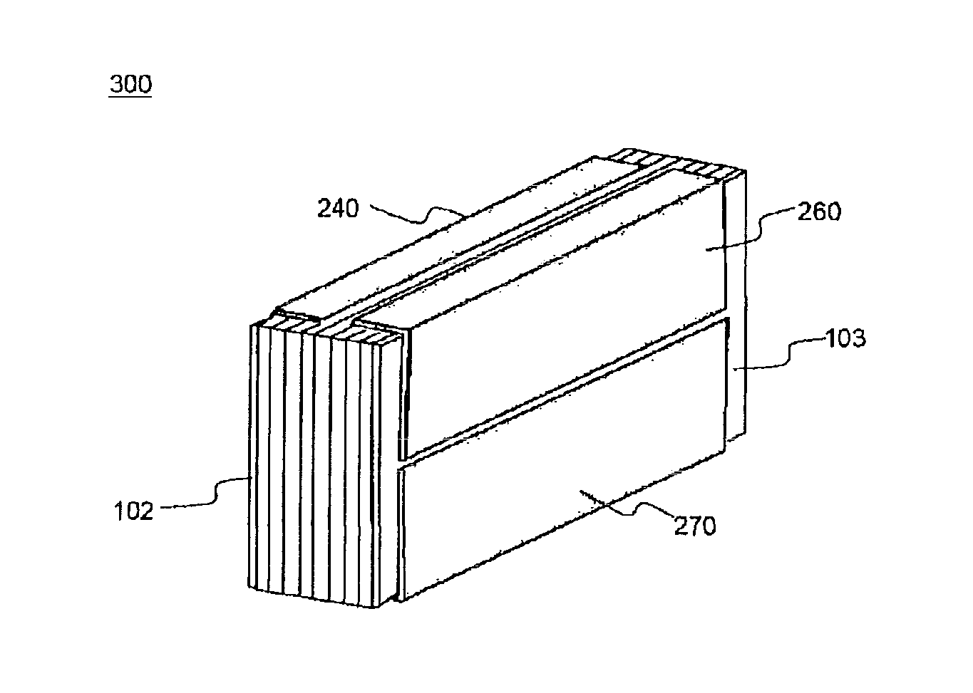
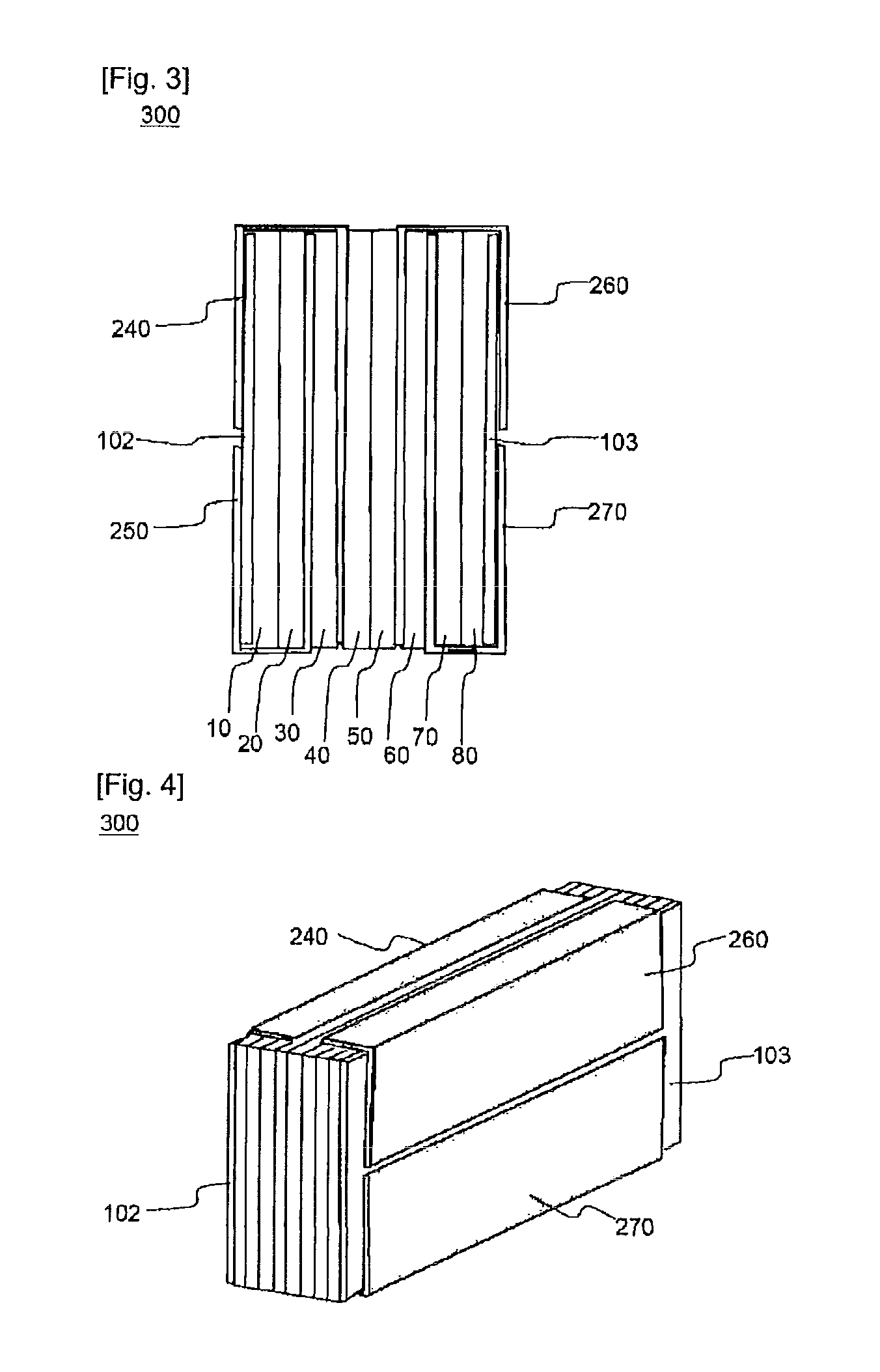
[0050]Referring to FIG. 1, the battery module 100 is constructed to have a structure in which four plate-shaped battery cells 10, 20, 30, and 40 are stacked while being adjacent to one another, and two heat dissipation members 200 and 210 are mounted at predetermined positions.

[0051]The first heat dissipation member 200 has one side to cover about one half W of the outer surface of the first battery cell 10. The second heat dissi...


PUM

PropertyMeasurementUnit
heat conductivityaaaaaaaaaa
sizeaaaaaaaaaa
weightaaaaaaaaaa

Abstract

Disclosed herein is a battery module including a plurality of sequentially stacked plate-shaped battery cells and two or more heat dissipation members, wherein the first heat dissipation member extends such that one side of the first heat dissipation member at least partially covers one outermost battery cell (a) of the battery module, and the other side of the first heat dissipation member is interposed between the inside battery cells, and the second heat dissipation member extends such that one side of the second heat dissipation member at least partially covers the outermost battery cell (a) while the second heat dissipation member is not overlapped with the first heat dissipation member, and the other side of the second heat dissipation member is interposed between the inside battery cells.

Description

TECHNICAL FIELD[0001]The present invention relates to a battery module including a plurality of sequentially stacked plate-shaped battery cells and two or more heat dissipation members, and, more particularly, to a battery module constructed to have a structure in which the first heat dissipation member extends such that one side of the first heat dissipation member at least partially covers one outermost battery cell (a) of the battery module, and the other side of the first heat dissipation member is interposed between the inside battery cells, and the second heat dissipation member extends such that one side of the second heat dissipation member at least partially covers the outermost battery cell (a) while the second heat dissipation member is not overlapped with the first heat dissipation member, and the other side of the second heat dissipation member is interposed between the inside battery cells.BACKGROUND ART[0002]Recently, a secondary battery, which can be charged and disc...

Claims


Application Information

Patent Timeline
Patent Type & Authority Patents(United States)
IPC IPC(8): H01M2/00H01M50/209H01M50/291H01M50/293
CPCH01M2/1077H01M2/1083H01M10/0413H01M10/5004H01M10/5032H01M10/5046H01M10/5063H01M10/5075H01M10/5016H01M10/625H01M10/647H01M10/6551H01M10/6567H01M10/6561H01M10/613Y02E60/10Y02P70/50H01M50/293H01M50/209H01M50/291H01M10/655
Inventor LEE, JIN KYUYOON, HEE SOOLEE, BUMHYUNKANG, DAL MOJANG, MINCHULYOON, JONGMOON
Owner LG ENERGY SOLUTION LTD
Features
  • R&D
  • Intellectual Property
  • Life Sciences
  • Materials
  • Tech Scout
  • Unparalleled Data Quality
  • Higher Quality Content
  • 60% Fewer Hallucinations
Learn More