Fuel cell system

Active Publication Date: 2005-05-19
HONDA MOTOR CO LTD
View PDF3 Cites 42 Cited by
  • Summary
  • Abstract
  • Description
  • Claims
  • Application Information

AI Technical Summary

Benefits of technology

[0012] A main object of the present invention is to provide a fuel cell system which makes it possible to simplify and downsize

Problems solved by technology

Therefore, it is not possible to supply the fuel gas equally to each of the fuel cells.
The piping system is complicated and large.
Thus, the operation of connecting the pipes is laborious, and the electrochemical fuel cell stack array 1 cannot

Method used


Image

  • Fuel cell system
  • Fuel cell system
  • Fuel cell system

Examples


Embodiment Construction

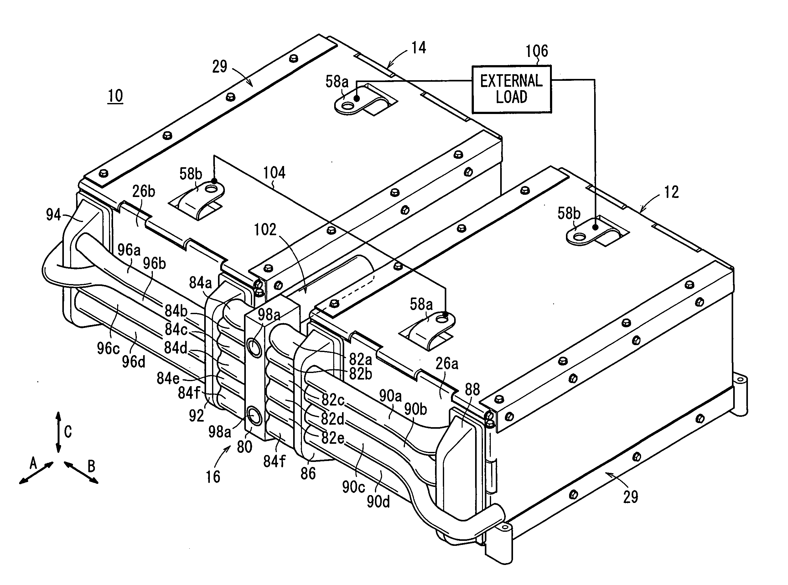
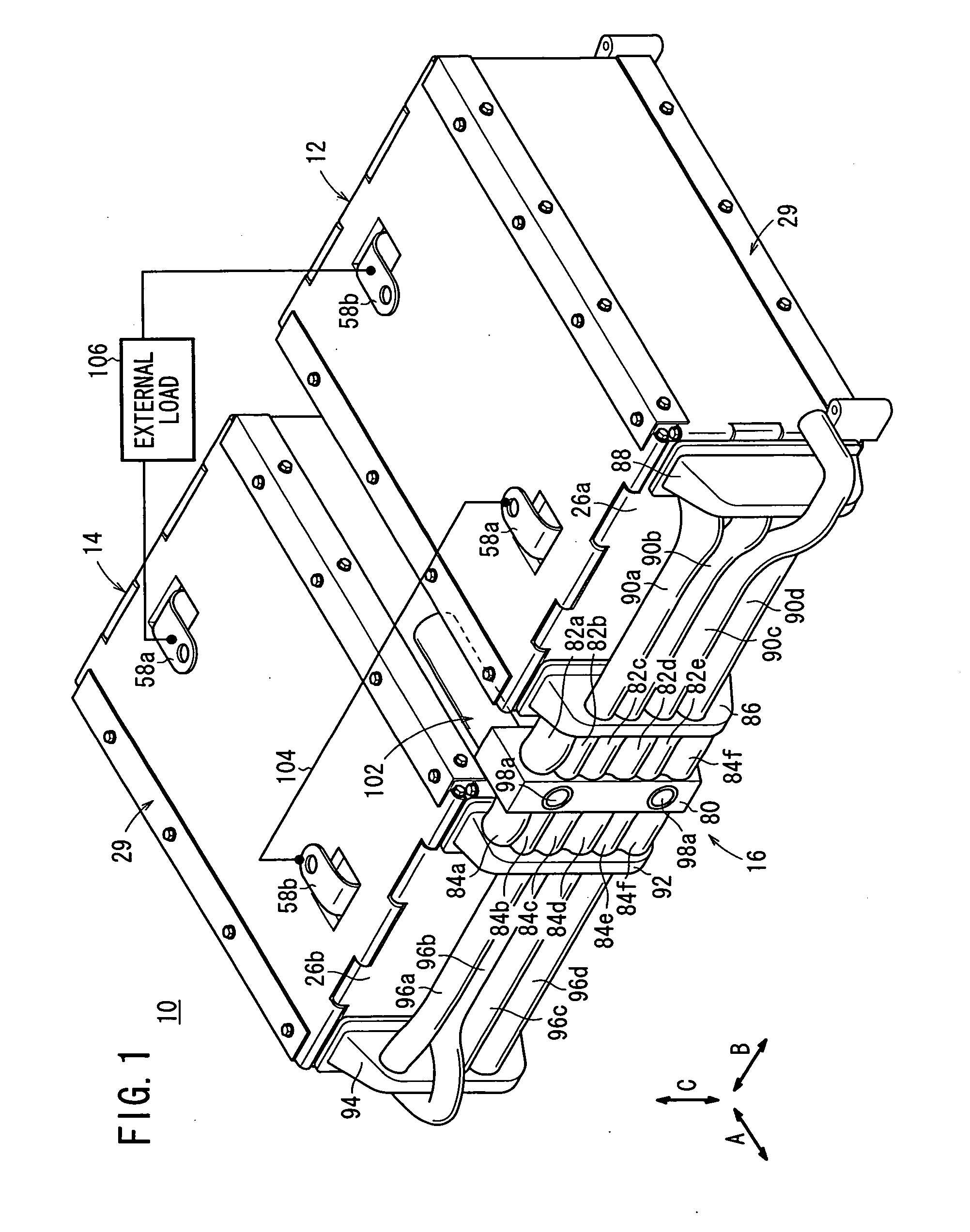
[0033]FIG. 1 is a perspective view schematically showing the overall structure of a fuel cell system 10 according to an embodiment of the present invention.

[0034] The fuel cell system 10 includes a first fuel stack 12 and a second fuel cell stack 14 having the same structure. The first fuel cell stack 12 and the second fuel cell stack 14 are juxtaposed in a horizontal direction such that the polarity of the first fuel cell stack 12 and the polarity of the second fuel cell stack 14 are oriented oppositely. An assembly manifold 16 is attached to a horizontal end of the first and second fuel cell stacks 12, 14.

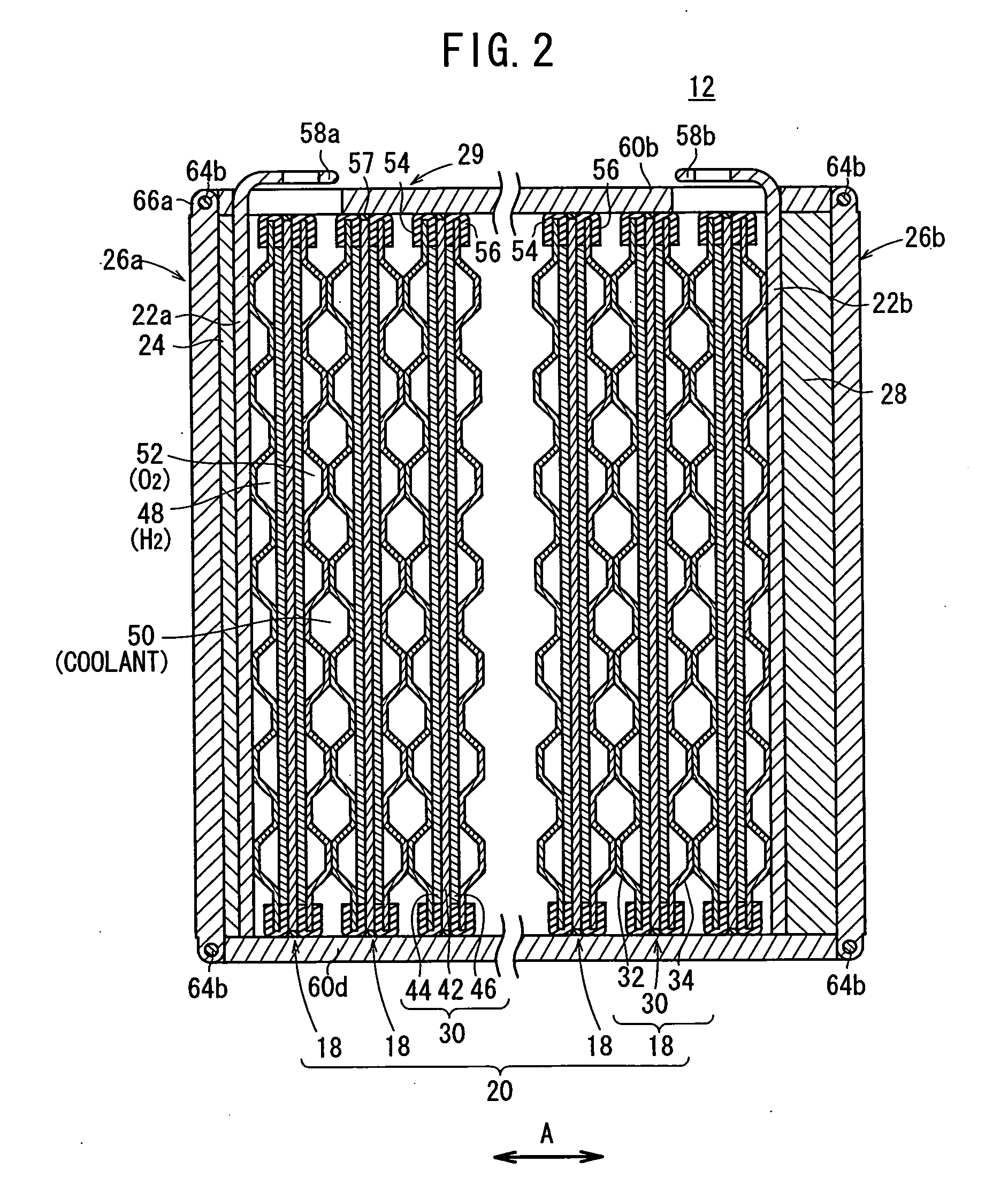
[0035] As shown in FIG. 2, the first fuel cell stack 12 includes a stack body 20 formed by stacking a plurality of unit cells 18 in a horizontal direction indicated by an arrow A. At an end of the stack body 20 in the stacking direction indicated by the arrow A, a terminal plates 22a is provided. An insulating plate 24 is provided outside the terminal plate 22a. Further, a firs...


PUM


Abstract

A fuel cell system includes first and second fuel cell stacks which are juxtaposed to each other. An assembly manifold is attached to the first and second fuel cell stacks. A connection block is provided at a central position of the assembly manifold. A fuel gas supply port and a fuel gas discharge port are provided on a front surface of the connection block, and an oxygen-containing gas supply port and an oxygen-containing gas discharge port are provided on a back surface of the connection block. A fuel gas and an oxygen-containing gas are equally supplied to each of the first and second fuel cell stacks.

Description

BACKGROUND OF THE INVENTION [0001] 1. Field of the Invention [0002] The present invention relates to a fuel cell system including a fuel cell stack formed by stacking a plurality of unit cells in a horizontal direction. Each of the unit cells includes an electrolyte electrode assembly and separators sandwiching the electrolyte electrode assembly. The electrolyte electrode assembly includes a pair of electrodes and an electrolyte interposed between the electrodes. Six fluid passages extend through the unit cells in the stacking direction. Three of the six fluid passages are provided on the left of the unit cells, and the other three of the six fluid passages are provided on the right of the unit cells. [0003] 2. Description of the Related Art [0004] For example, a solid polymer fuel cell employs a membrane electrode assembly which includes an anode and a cathode, and an electrolyte membrane (electrolyte) interposed between the anode and the cathode. The electrolyte membrane is a poly...

Claims


Application Information

Patent Timeline
IPC IPC(8): H01M8/00H01M8/02H01M8/04H01M8/24
CPCH01M8/04029H01M8/04089H01M8/2415Y02E60/50H01M8/2485H01M8/249H01M8/2475H01M8/0267
Inventor SATO, MASAHIKONISHIYAMA, TADASHI
Owner HONDA MOTOR CO LTD
Why Eureka
Try Eureka