Method and apparatus to promote non-stationary flame

a non-stationary flame and flame retardant technology, applied in lighting and heating apparatus, combustion types, combustion using lumps and pulverulent fuels, etc., can solve problems such as damage to enclosures, excessive oxidation of materials, and inability to achieve optimal arrangement, etc., to achieve uniform temperature of material surfa

Inactive Publication Date: 2007-02-15
PRAXAIR TECH INC
View PDF13 Cites 43 Cited by
  • Summary
  • Abstract
  • Description
  • Claims
  • Application Information

AI Technical Summary

Benefits of technology

[0005] The present invention provides a method and apparatus that are useful in permitting combustion to be carried out in a manner that affords a more uniform temperature of the surface of the material to be heated, or heated and melted.

Problems solved by technology

Such arrangements are not necessarily as efficient as possible, because the temperatures at various points around the outer surface of the flame and along the length of the flame are not uniform so that there is a region of the flame that has the highest temperature and heat flux to the material.
This lack of uniformity means that the position of the burner relative to the material being heated, and the conditions under which the burner is operated, must be set so that the highest temperatures and heat flux generated by the burner are not so high as to produce unwanted results such as “hot spots”0 in the material or the enclosure in which the combustion is being carried out, excessive oxidation of the material, or damage to the enclosure.
However, doing so often requires accepting temperatures at other points around the flame that are not as high as could be tolerated, and thereby requires accepting less than optimum performance of the burner.
This lack of efficiency has heretofore been considered acceptable for a number of reasons including the absence of a useful method and apparatus that can provide greater uniformity of temperature.

Method used


Image

  • Method and apparatus to promote non-stationary flame
  • Method and apparatus to promote non-stationary flame
  • Method and apparatus to promote non-stationary flame

Examples


Embodiment Construction

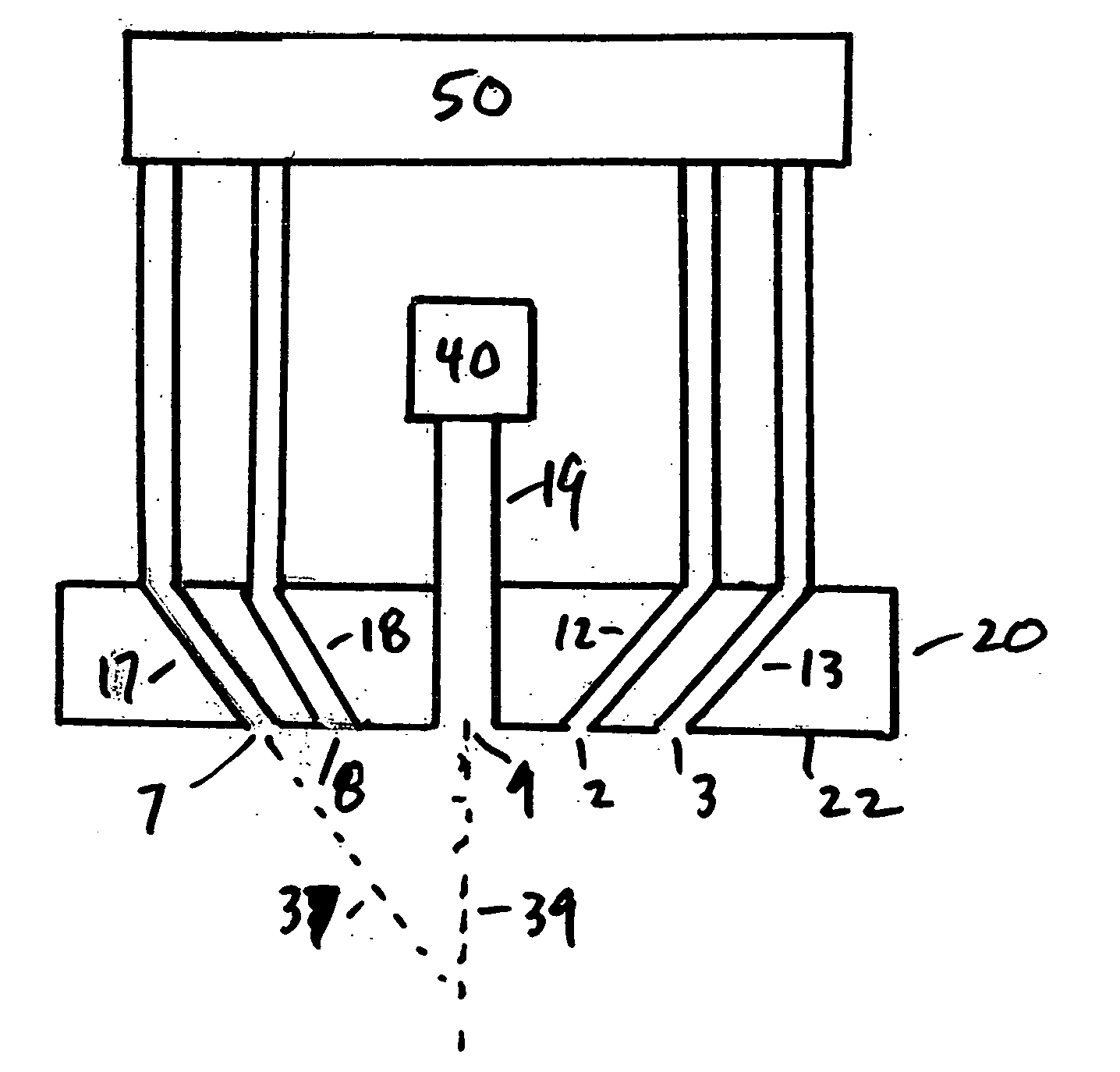
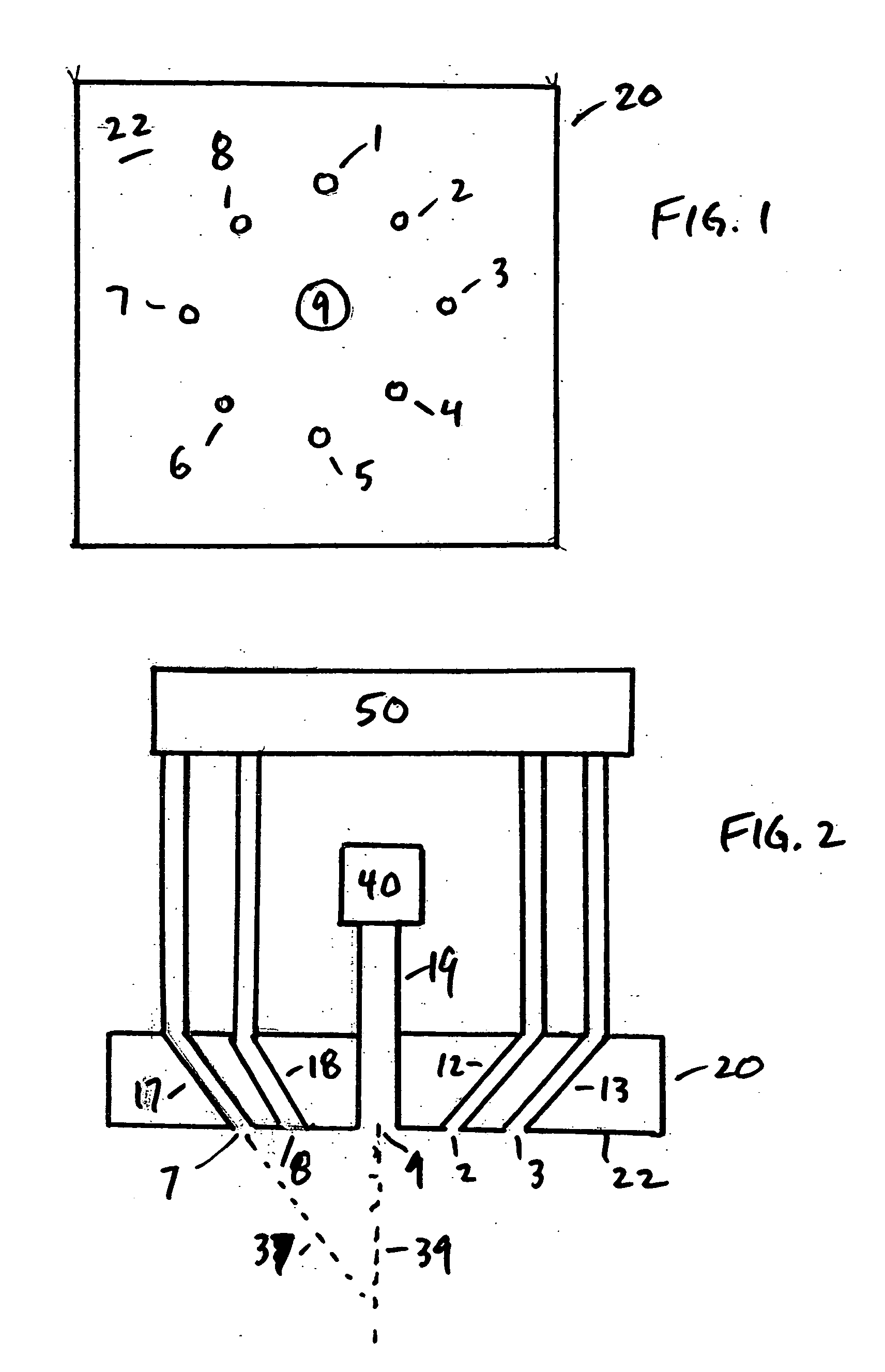
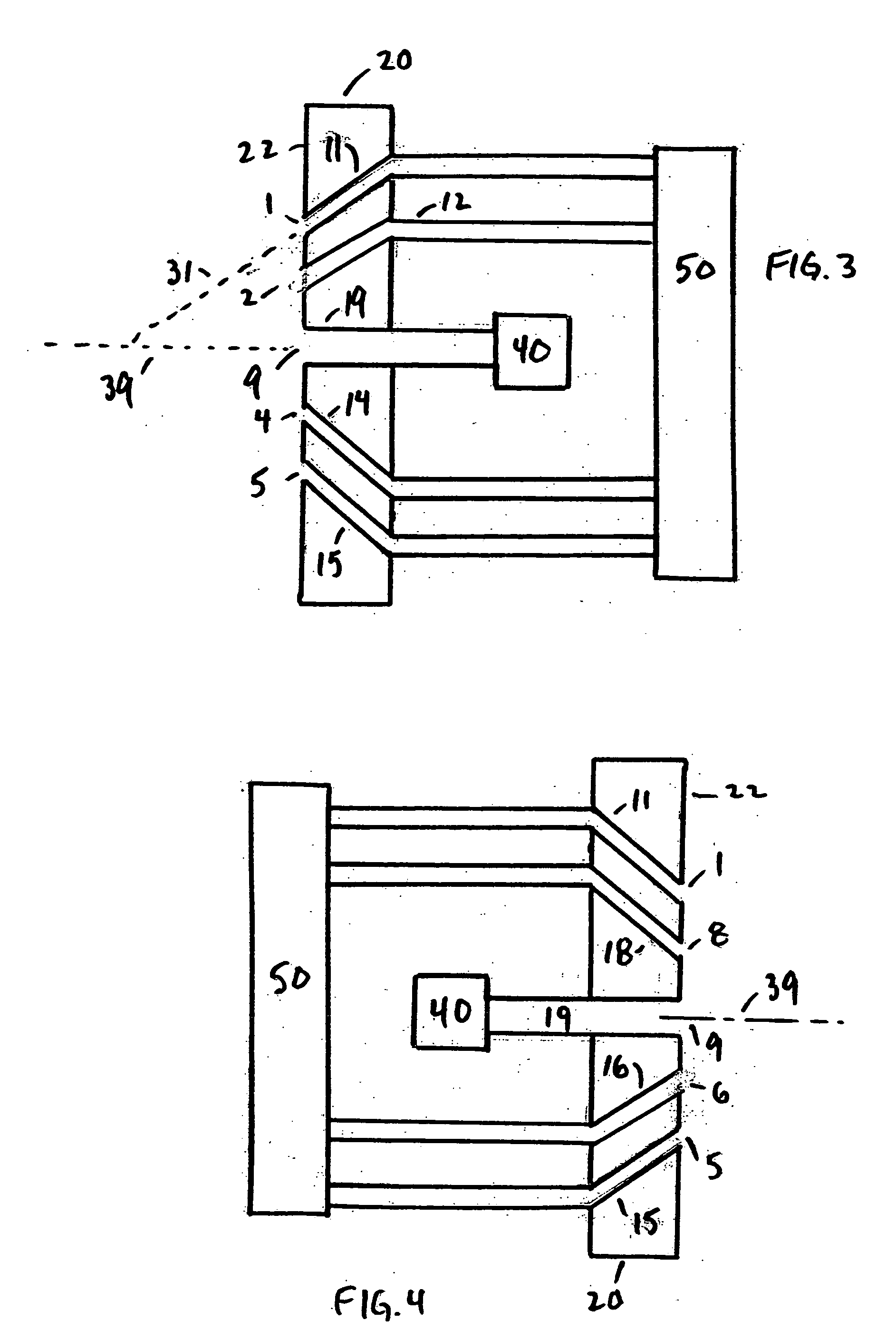
[0041] The burner according to the present invention is generally referred to as 20 in FIGS. 1-4. Burner 20 is preferably formed of refractory material that is capable of retaining its shape and composition when exposed to the temperatures of 1000° F. to 3000° F. to which the burner may be exposed. Examples of such materials include alumina, silica, AZS (alumina-zirconia-silica), mullite, zirconia, and zirconite. Burner 20 can be part of a roof, side wall or bottom of an enclosure such as a furnace in which the desired combustion is carried out.

[0042] Central feed port 9 and outer ports 1 through 8 open in the front 22 of burner 20. Central feed port 9 and the outer ports may be, but are not required to be, in the same plane, so long as the other characteristics described herein are observed. Central feed port 9 can comprise one opening as shown in FIG. 1, or can comprise two or more openings (preferably 1 to 8, more preferably 1 to 3) openings which should be located close to each...


PUM


Abstract

A burner has a central port and 3 or more outer ports whose axes are angled toward or away from the central port axis. Sequentially varying the outer port(s) from which material is injected at a high enough momentum to deflect the flame from the axis of the central port changes the orientation of the flame with respect to the central port axis.

Description

FIELD OF THE INVENTION [0001] The present invention relates to methods and apparatus useful in carrying out combustion. BACKGROUND OF THE INVENTION [0002] Many industrial processes require subjecting material to elevated temperatures on the order of 1000° F. to 3000° F. Examples of such processes include melting aluminum and other metals, maintaining molten metal in the molten state, melting glassmaking materials, and maintaining glass in the molten state. To generate the required elevated temperature, processes requiring such elevated temperatures often combust carbonaceous fuel, in one or more burners each of which produces a flame situated close enough to the material that the heat of combustion establishes the desired elevated temperature in the material. [0003] Typically the one or more burners used for this purpose each generate a flame that extends outward from the burner in a fixed position, such as extending from a side wall of a furnace across and over the top of a portion...

Claims


Application Information

Patent Timeline
Patent Type & Authority Applications(United States)
IPC IPC(8): F23C5/00F23D99/00
CPCF23D14/22F23D17/00F23D99/003F23M2900/05021F23D2900/00006F23D2900/00013F23D2204/00F23D91/02F23D91/00
Inventor KOBAYASHI, WILLIAM THORUTASCA, ABILIOMEAGHER, JAMES PATRICKKAILBURN, MARK ALLEN
Owner PRAXAIR TECH INC
Why Eureka
Try Eureka