Light emitting diode apparatus

a technology apparatuses, which is applied in the direction of electrical apparatus, semiconductor devices, instruments, etc., can solve the problems of increasing the cost of light emitting diodes, the efficiency of phosphor layer stability is not stable, and the color or luminous intensity of arrayed light emitting diodes may appear. , to achieve the effect of facilitating different light incident angles, facilitating light mixing effects, and reducing the effect of phosphor layer stability

Active Publication Date: 2012-07-24
AU OPTRONICS CORP
View PDF30 Cites 25 Cited by
  • Summary
  • Abstract
  • Description
  • Claims
  • Application Information

AI Technical Summary

Benefits of technology

[0008]The present invention proposes a light emitting diode apparatus, which utilizes light diffusing means to achieve better light mixing effect so that the light emitting diode apparatus can select the light emitting elements in a larger numerical range of bin codes. In addition, a sealing material is used to separate a phosphor layer so that the phosphor layer is not affected by heat and the efficiency of the phosphor layer can remain stable. Further, having light convergent and light divergent functions in different directions can facilitate different light incident angles in different directions.

Problems solved by technology

However, when a plurality of light emitting diodes are arrayed for an application and are not first sorted, noticeable variations in color or luminous intensity may appear.
When an array of light emitting diodes is prepared for use, light emitting diodes having similar bin codes are selected so that arrayed light emitting diodes will not have non-uniformity issues.
Nevertheless, the sorting of light emitting diodes increases cost, and in addition, with the utilization of devices for large luminous area and the requirement of luminous quality, the numerical range of bin codes selected for an array of light emitting diodes is relatively narrowed, and the narrowing of the numerical range of bin codes causes inconvenience and cost increase.
Furthermore, the efficiency of phosphor powder declines with increasing in environmental temperature.
Light emitting diodes are luminous devices with high heat generation, and if the design of the heat dissipation module is improper or the control of environmental conditions is poor, the efficiency of the phosphor powder will be affected.
In summary, use of sorted light emitting diodes to make arrayed light emitting diodes can ensure the luminous quality; however, high cost will affect economic benefit.
Moreover, when light emitting diodes are used in a backlight module, the light projection angles varying in different directions is required, but in the prior art techniques, no technology has been developed to address this issue.

Method used


Image

  • Light emitting diode apparatus
  • Light emitting diode apparatus
  • Light emitting diode apparatus

Examples


first embodiment

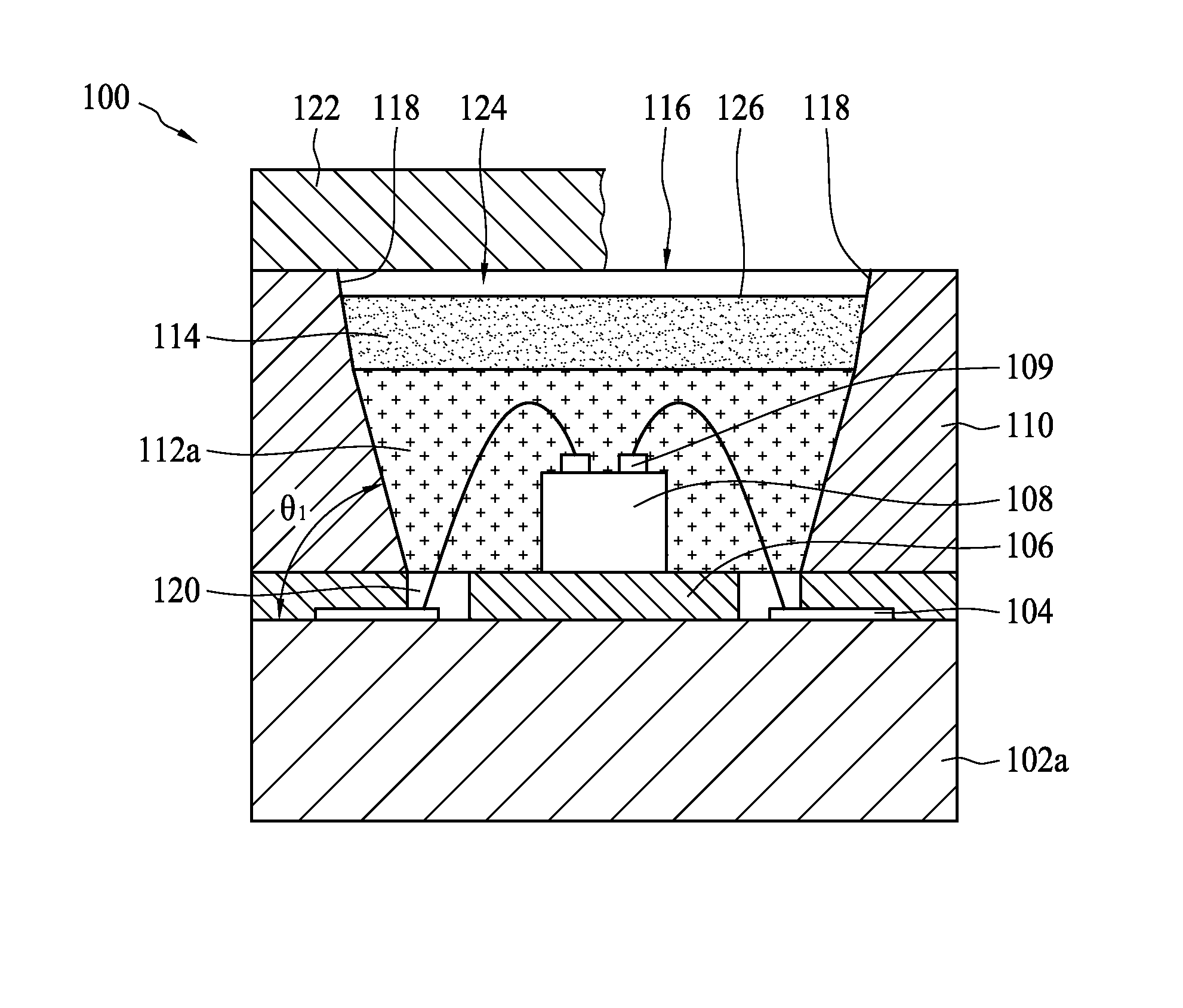
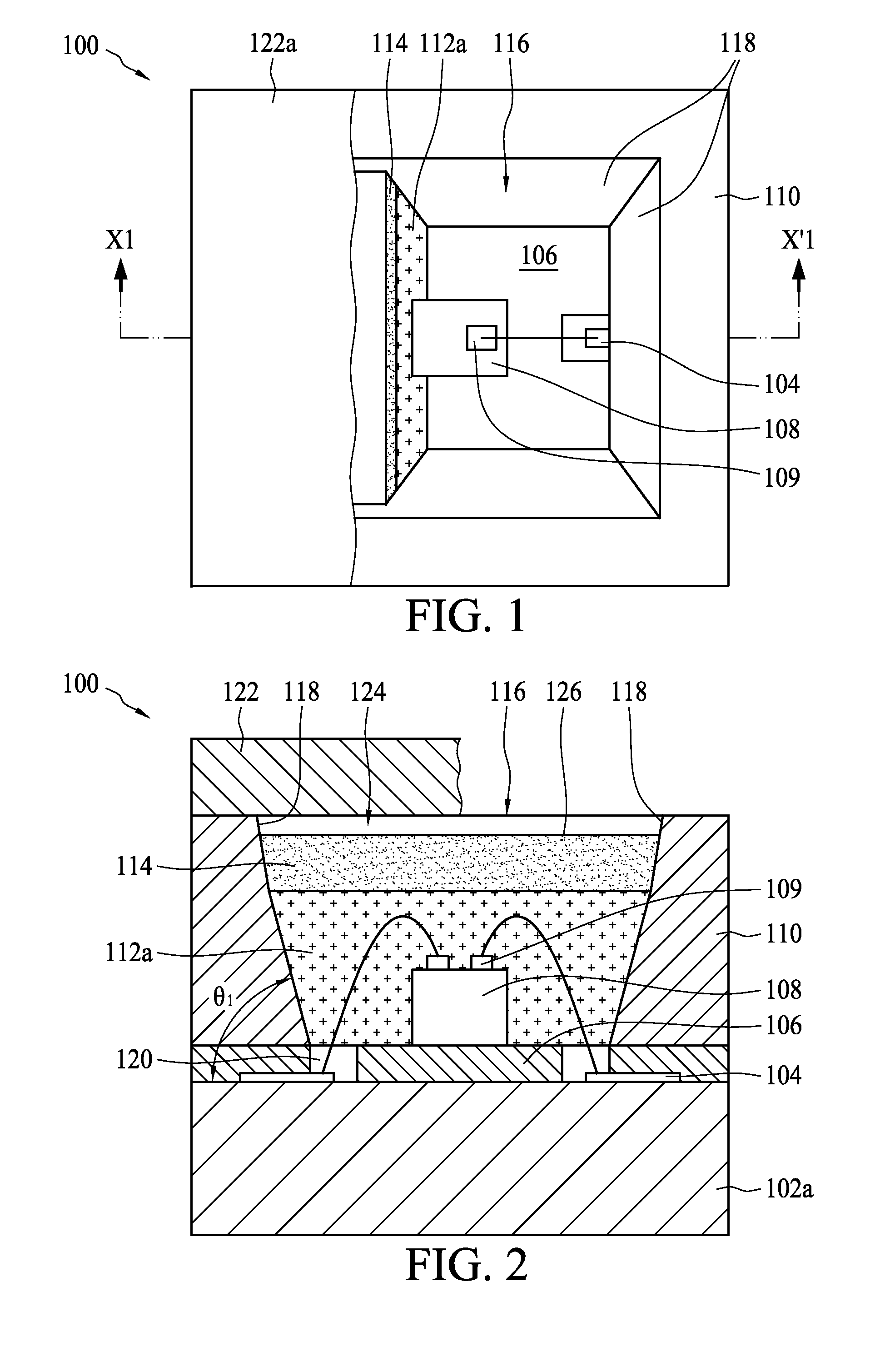
[0026]FIG. 1 is a schematic top view showing a light emitting diode apparatus 100 according to the present invention. FIG. 2 is a sectional view along section line X1-X′1 of FIG. 1. The light emitting diode apparatus 100 comprises a substrate 102a having a circuit pattern 104, a reflection layer 106 disposed on the substrate 102a, at least one light emitting element 108 disposed on the reflection layer 106, a reflector 110 surrounding the light emitting element 108, a sealing material 112a disposed around the at least one light emitting element 108, and a phosphor layer 114 disposed on the sealing material 112a and configured to provide uniformly mixed light. The light emitting element 108 comprises a conductive portion 109, and the circuit pattern 104 of the substrate 102a is coupled to the conductive portion 109, and thereby transmits power to the light emitting element 108.

[0027]The reflector 110 comprises a light emitting opening 116 on the exterior of the reflector 110 and a fi...

second embodiment

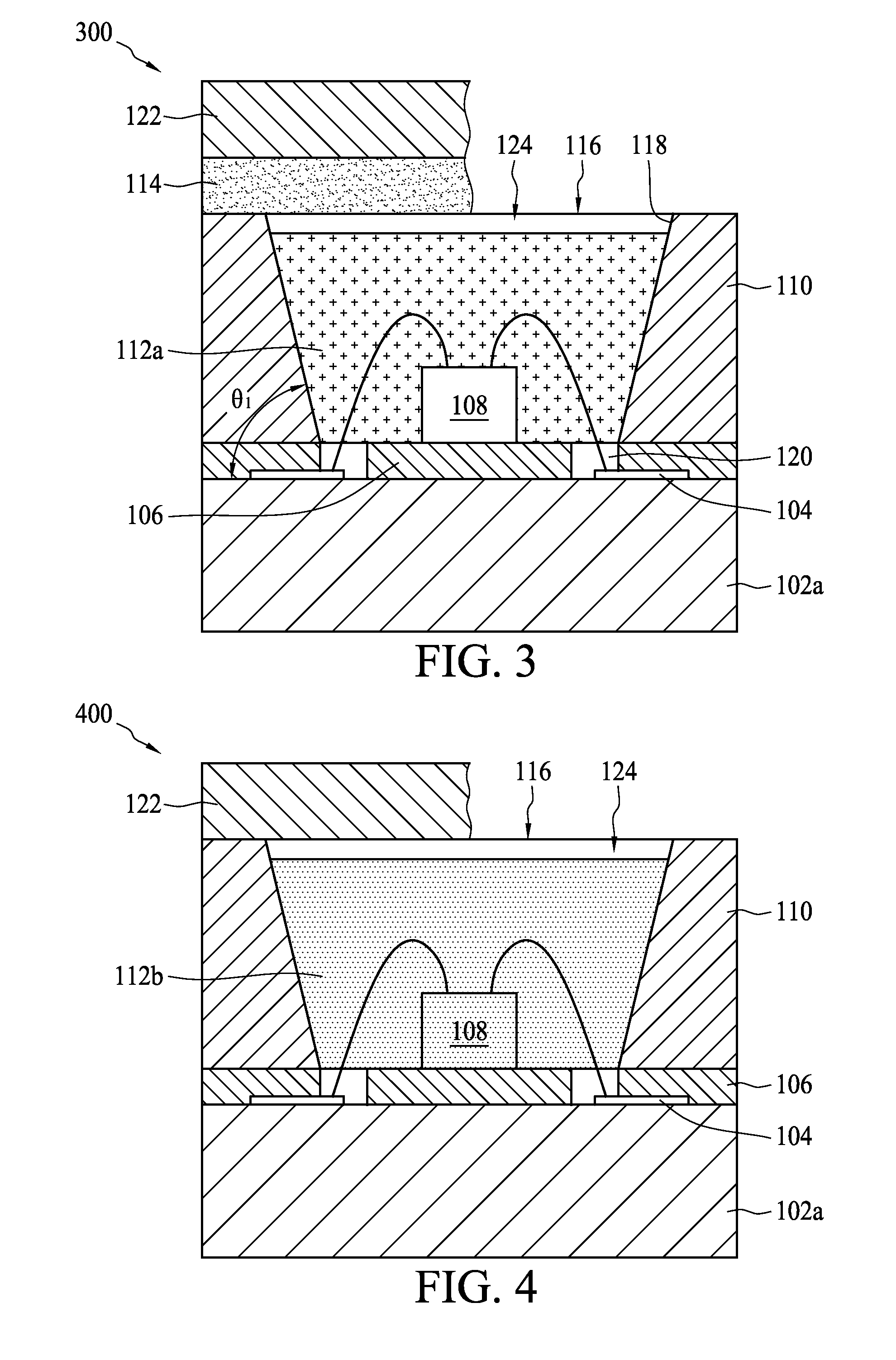
[0033]FIG. 3 shows a sectional view of a light emitting diode apparatus 300 according to the present invention. The light emitting diode apparatus 300 comprises a substrate 102a having a circuit pattern 104, a reflection layer 106 disposed on the substrate 102a, at least one light emitting element 108 disposed on the reflection layer 106, a reflector 110 surrounding the at least one light emitting element 108, and a sealing material 112a disposed around the at least one light emitting element 108. The reflector 110 comprises a light emitting opening 116 at the exterior of the reflector 110 and at least one optical microstructure film 122 disposed on the light emitting opening 116. A phosphor layer 114 is formed on the optical microstructure film 122 and is located between the optical microstructure film 122 and the light emitting opening 116, and thereby achieves uniform light mixing effect. The phosphor layer 114 is separated from the substrate 102a so that the phosphor layer 114 w...

third embodiment

[0034]FIG. 4 shows a sectional view of a light emitting diode apparatus 400 according to the present invention. The light emitting diode apparatus 400 comprises a substrate 102a having a circuit pattern 104, a reflection layer 106 disposed on the substrate 102a, at least one light emitting element 108 disposed on the reflection layer 106, a reflector 110 surrounding the light emitting element 108, and a sealing material 112b disposed around the at least one light emitting element 108, wherein the sealing material 112b is blended with phosphor powder. Within the sealing material 112b, light scattering particles can be interdispersed to uniformly diffuse passing light. The reflector 110 comprises a light emitting opening 116 at the exterior of the reflector 110 and at least one optical microstructure film 122 is disposed on the light emitting opening 116. In the present embodiment, the sealing material 112b is separated from the optical microstructure film 122 by a gap 124. In another...


PUM


Abstract

A light emitting diode apparatus comprises a substrate having a circuit pattern, a reflection layer disposed on the substrate, at least one light emitting element disposed on the reflection layer, a reflector disposed around the at t one light emitting element, a sealing material formed over the at least one light emitting element and a phosphor layer disposed over the sealing material. The light emitting element comprises a conductive portion electrically coupled to the circuit pattern. In one embodiment, a plurality of light emitting elements are linearly arrayed, and a spacer is disposed between every two adjacent light emitting elements.

Description

BACKGROUND OF THE INVENTION[0001]1. Field of the Invention[0002]The present invention relates to a light emitting diode device, and relates more particularly to a light emitting diode device of high light-mixing efficiency that can have larger selection range of bins of light emitting diodes.[0003]2. Description of the Related Art[0004]Due to variations in manufacturing processes, characteristics such as intensities or wavelengths of fabricated light emitting diodes vary from one to another. When light emitting diodes were first introduced as lighting sources, most lighting sources utilized a single light emitting diode. In such arrangements, the influence of the variations between light emitting diodes is not significant.[0005]However, when a plurality of light emitting diodes are arrayed for an application and are not first sorted, noticeable variations in color or luminous intensity may appear. To solve such issue, light emitting diodes are usually characterized in accordance wit...

Claims


Application Information

Patent Timeline
Patent Type & Authority Patents(United States)
IPC IPC(8): H01L29/18H01L33/00
CPCH01L33/507G02F1/133603G02F1/133606H01L25/0753H01L2224/48227H01L2224/48228H01L33/60H01L2224/48091H01L2924/00H01L2924/181H01L2924/00014H01L2924/00012
Inventor HUNG, CHUN CHANGSHAO, TUNG LIANGLIN, FALCON
Owner AU OPTRONICS CORP
Why Eureka
Try Eureka