Light-mixed layer and method for mixing lights

A light mixing layer and light source technology, applied in electrical components, electric solid devices, circuits, etc., can solve the problems of low brightness and poor effect, and achieve the effect of reducing light consumption and good light mixing effect.

Inactive Publication Date: 2004-02-25
何文志
View PDF0 Cites 8 Cited by
  • Summary
  • Abstract
  • Description
  • Claims
  • Application Information

AI Technical Summary

Problems solved by technology

It can be seen from the figure that although the existing light mixing method can produce the required light wavelength, its effect is not good, and the brightness is also low

Method used


Image

  • Light-mixed layer and method for mixing lights
  • Light-mixed layer and method for mixing lights
  • Light-mixed layer and method for mixing lights

Examples


Embodiment Construction

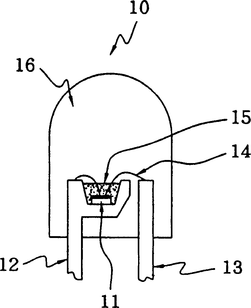
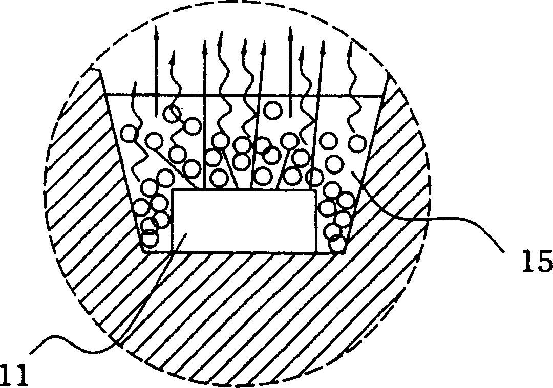
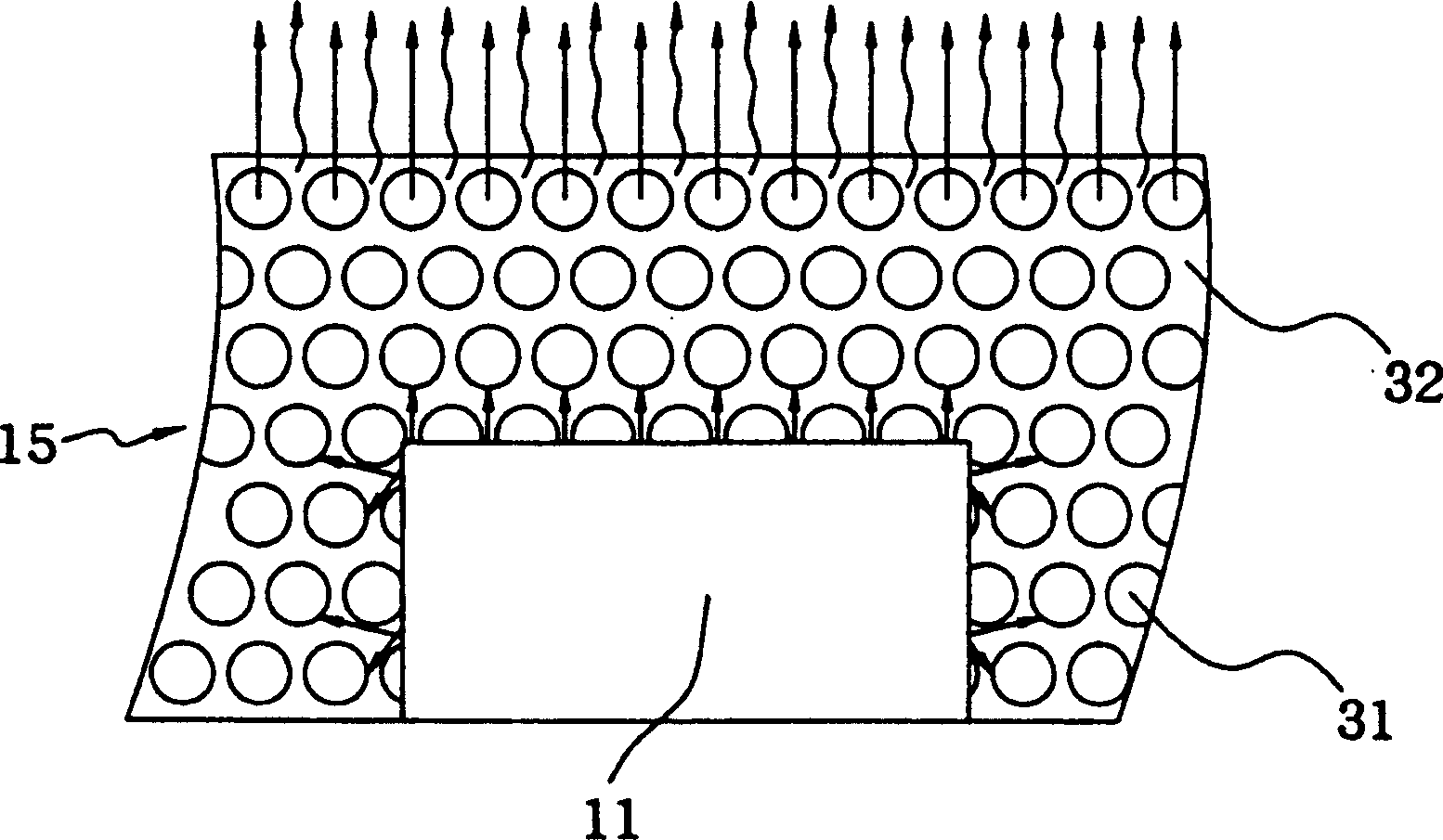
[0034] see Image 6 One embodiment of the light-mixing layer 61 of the present invention is set in the crystal cup 63, and can cover the light-emitting diode chip 62 by mixing with resin or coating, the purpose of which is to make the light-mixing layer 61 completely The light source emitted by the LED chip 62 is absorbed. The light mixing layer 61 is composed of scatterer particles 64, phosphor particles 65 and diffuser particles 66. The scatterer particles 64 can be made of quartz, glass or other polymer light-transmitting materials. The phosphor particles 65 can be selected Phosphor particles, the diffuser particles 66 can be made of barium titanyl oxide, titanium oxide, or silicon oxide. After heating and baking or UV ultraviolet irradiation, the scatterer particles 64, phosphor particles 65, and diffuser particles 66 will be able to use the gravity sedimentation method, telecentric sedimentation method, penetrating force method, pressurization method, and coagulation met...


PUM


Abstract

The present invention discloses a light-mixing layer and its light-miting method. When the light-mixing device is made, said invention adopts the processing mode to make the particles of all the components in the light-mixing layer produce alternative arrangement, so that after the light wavelength provided by light-emitting source is absorbed by said light-mixing layer, it can make the fluorescent body particles be excited to produce another light wavelength, and said two different light wavelengths are collected in the light-mixing layer so as to can obtain full light diffusion, light conversion and light mixing, after the lights are mixed, a high-uniformity, high-luminance and constant light source can be produced.

Description

technical field [0001] The invention relates to a light mixing device, in particular to a light mixing layer and a light mixing method. Background technique [0002] Light Emitting Diode (Light Emitting Diode referred to as LED) has been widely used in daily life. Due to its advantages of small size, low power consumption, low heat generation and long life, it has gradually replaced traditional light bulbs as lighting. equipment. In particular, the successful development of high-brightness light-emitting diodes and white light-emitting diodes has opened up the application of light-emitting diodes in display panels and indoor lighting. [0003] A conventional light-emitting diode assembly is disclosed in Taiwan Patent Publication No. 383508, titled "Light-Emitting Device and Display Device". The existing light-emitting diode assembly includes a light-emitting diode chip, a phosphor, and an epoxy resin. It utilizes the light wavelength emitted by the light-emitting diode chi...

Claims


Application Information

Patent Timeline
Patent Type & Authority Applications(China)
IPC IPC(8): H01L33/00H01L33/50
CPCH01L2224/48091H01L2224/48247H01L2224/48257H01L2924/181
Inventor 何文志
Owner 何文志
Why Eureka
Try Eureka