transparent display device

A transparent display and light-transmitting area technology, which is applied to identification devices, semiconductor/solid-state device parts, instruments, etc., can solve the problem of low transparency of transparent display devices, inability to clearly observe the background of display devices, and poor transparency of transparent display devices, etc. problem, to achieve the effect of good visible light transmittance

Active Publication Date: 2021-03-09
IND TECH RES INST +1
View PDF11 Cites 0 Cited by
  • Summary
  • Abstract
  • Description
  • Claims
  • Application Information

AI Technical Summary

Problems solved by technology

[0003] If the transparency of the transparent display device is too low, the user will obviously observe the existence of the display device itself, but cannot clearly observe the background behind the display device
In addition, if the transparent display device is to have a touch sensing function, the transparency of the transparent display device is likely to be deteriorated due to the arrangement of electrodes and wiring for touch sensing.
There is still much room for improvement in transparent display devices

Method used


Image

  • transparent display device
  • transparent display device
  • transparent display device

Examples


Embodiment Construction

[0080] In order to make the above-mentioned features and effects of the present invention more clear and understandable, the following specific examples are given together with the accompanying drawings for detailed description as follows.

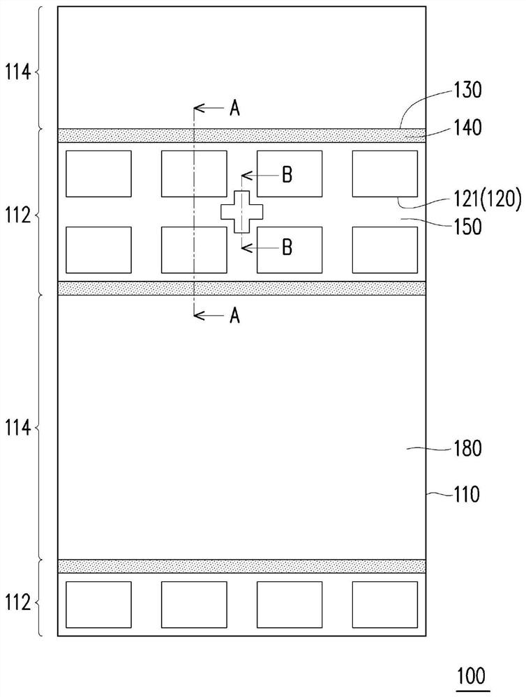
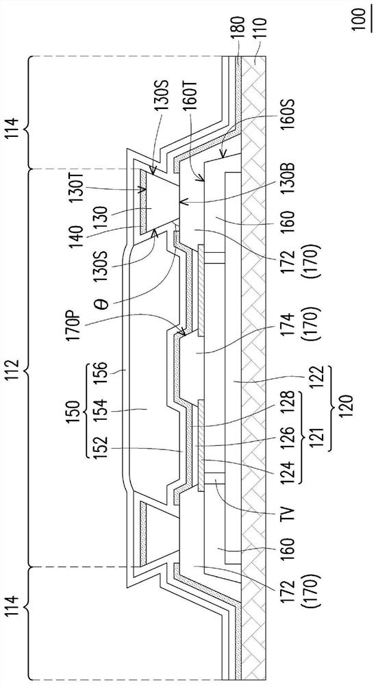
[0081] figure 1 It is a schematic partial top view of a transparent display device according to an embodiment of the present invention. Depend on figure 1 It can be seen that the transparent display device 100 includes a substrate 110 , a light emitting element 120 , a first wall structure 130 and a first top conductive pattern 140 . Both the light emitting element 120 and the first wall structure 130 are disposed on the substrate 110 . The first top conductive pattern 140 is disposed on the top surface of the first retaining wall structure 130 . figure 1 The first top conductive pattern 140 in the overlaps with the first wall structure 130, and figure 1 The distribution area of ​​the first top conductive pattern 140 is represented in ...


PUM


Abstract

The invention relates to a transparent display device comprising a substrate, a light-emitting element, a first barrier wall structure, a first top conductive pattern and a barrier encapsulation multilayer structure. The substrate has a light-emitting area and a light-transmitting area. The light emitting element is located in the light emitting area. The first retaining wall structure has undercut sidewalls. The first barrier structure is the junction of the light-transmitting area and the light-emitting area, and the light-emitting element is located in the light-emitting area surrounded by the first barrier structure. The first top conductive pattern is configured on the top surface of the first retaining wall structure. The barrier encapsulation multilayer structure is configured on the light emitting element. The barrier encapsulation multilayer structure includes a first barrier layer and a second barrier layer. A portion where the first barrier layer and the second barrier layer overlap each other is located in the light emitting area surrounded by the first retaining wall structure.

Description

technical field [0001] The invention relates to a transparent display device. Background technique [0002] The transparent display device itself has a certain degree of transparency, which can not only display information or pictures, but also allow users to clearly see the background behind the display. Transparent display devices can be used in various applications such as building windows, automobile windows, and shop windows, and thus attract market attention. [0003] If the transparency of the transparent display device is too low, the user will obviously observe the existence of the display device itself, but cannot clearly observe the background behind the display device. In addition, if the transparent display device is to have a touch sensing function, the transparency of the transparent display device will be easily deteriorated due to the arrangement of electrodes and wires for touch sensing. There is still much room for improvement in transparent display devi...

Claims


Application Information

Patent Timeline
Patent Type & Authority Patents(China)
IPC IPC(8): G09F9/30
CPCG09F9/30H01L23/31H01L23/3157G06F3/044G06F3/0412H10K59/122H10K59/131H10K50/822H10K50/844H10K59/40
Inventor 蔡宜修蔡宇翔张志嘉陈冠廷陈光荣蔡玉堂
Owner IND TECH RES INST
Why Eureka
Try Eureka