Electro luminescence line and preparation method thereof

A technology of electroluminescent wires and luminescent substances, which is applied in the field of electroluminescent light sources, can solve the problems of limited improvement in the brightness of electroluminescent wires, increase the complexity of the structure of electroluminescent wires, and affect the overall brightness of electroluminescent wires. Achieve the effect of stable and reliable optical continuity, strong affinity and brightness improvement

Inactive Publication Date: 2006-02-08
武汉依奥光电子材料有限公司
View PDF1 Cites 0 Cited by
  • Summary
  • Abstract
  • Description
  • Claims
  • Application Information

AI Technical Summary

Problems solved by technology

But what this filler mainly selects is the viscous liquid substance, and it also has the following problems: one, because the pores formed in the fluorescent substance layer are of different sizes, the particles of the liquid filler used The diameter is often larger than the diameter of some pores, so there will inevitably be some pores that cannot be filled, resulting in the loss of light energy in this part of the pores, and dark spots cannot be eliminated; second, even if the pores are filled with liquid fillers, due to This kind of neutral filling will not form a new electric field around the pores to excite the fluorescent particles to emit light, so the improvement of the brightness of the electroluminescence line is limited; thirdly, the liquid filling can easily penetrate into the pores, It can also be easily leaked or evaporated from the pores. In order to effectively prevent the loss of liquid filling, a transparent viscous insulating material needs to be coated outside the fluorescent material layer as a barrier layer, which not only increases the electroluminescence. The complexity of the structure of the luminescent line also increases the difficulty of its manufacturing process. More importantly, the blocking layer blocks or scatters part of the light source while blocking the filling, which affects the overall brightness of the electroluminescent line.

Method used


Image

  • Electro luminescence line and preparation method thereof
  • Electro luminescence line and preparation method thereof
  • Electro luminescence line and preparation method thereof

Examples


Embodiment Construction

[0016] Below in conjunction with accompanying drawing, specific embodiment of the present invention is described in further detail:

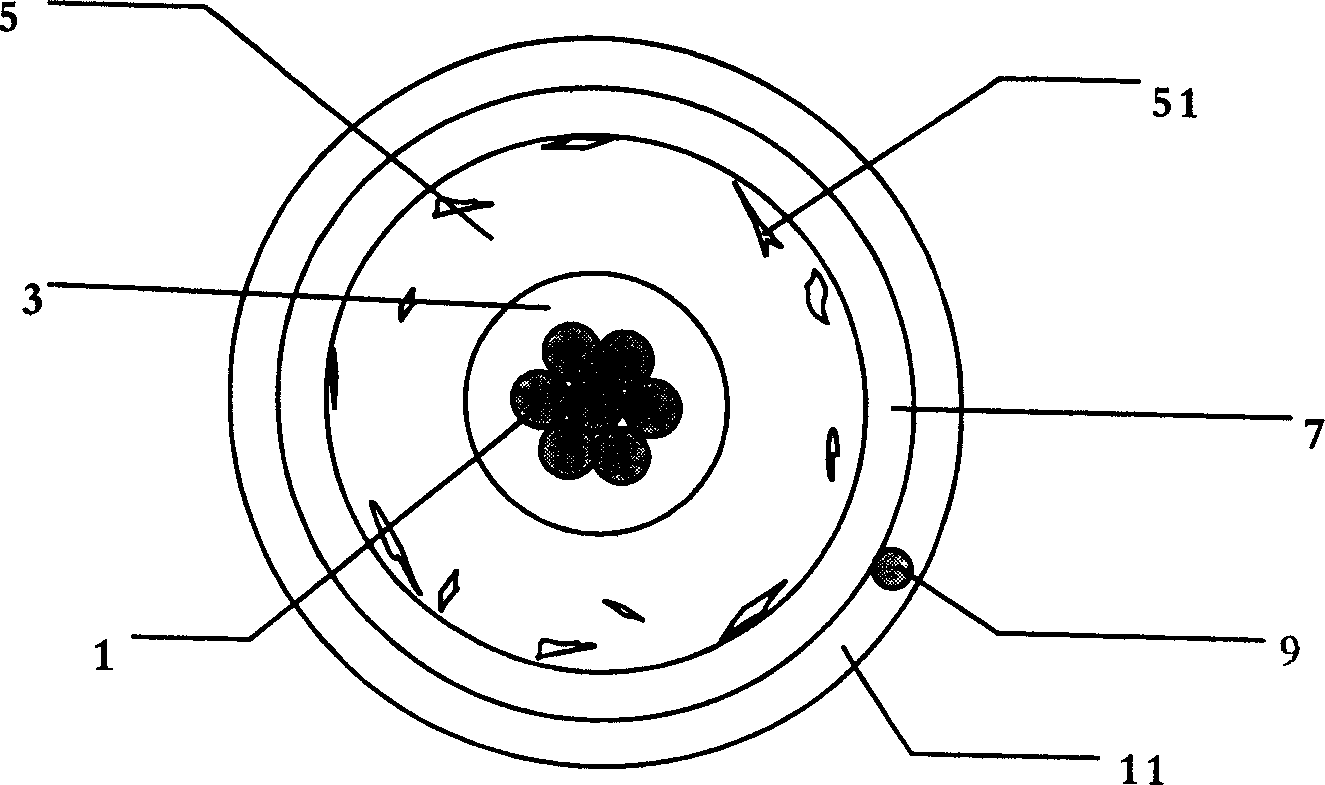
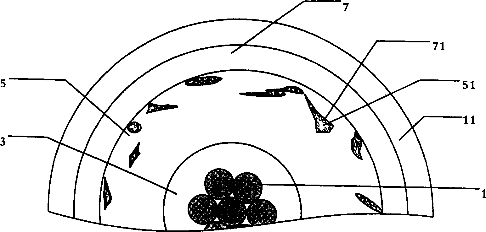
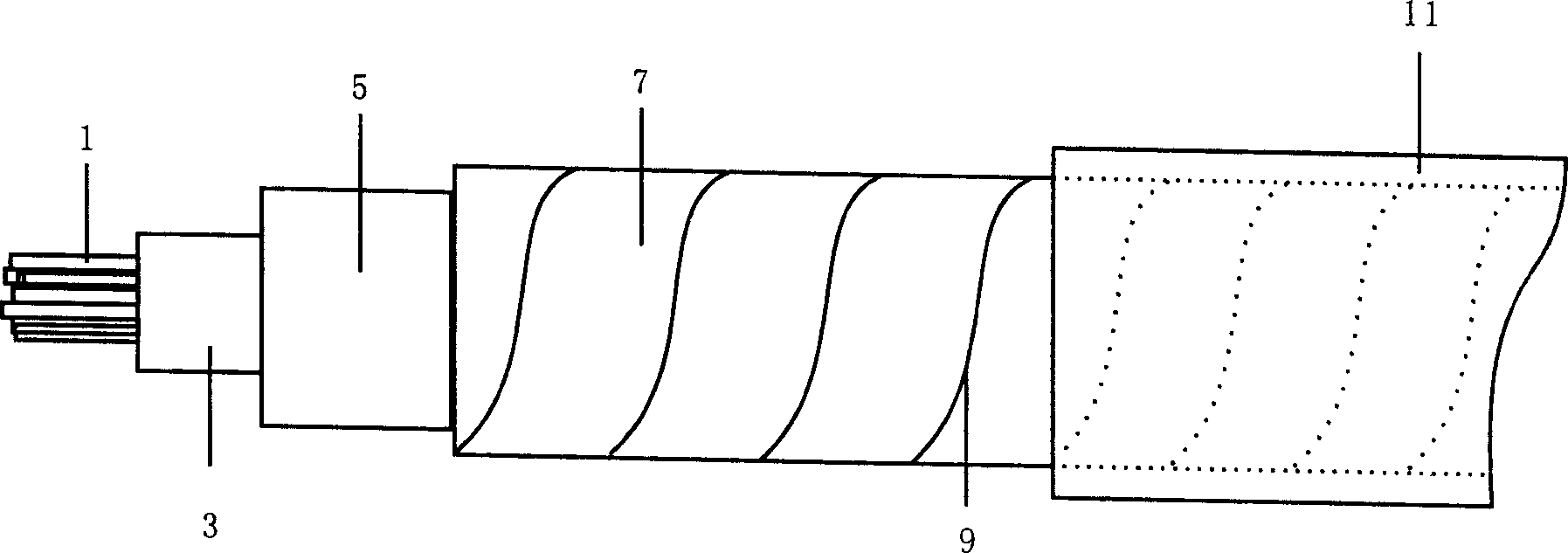
[0017] Such as Figure 1 to Figure 3 The electroluminescence wire shown has a central electrode 1 composed of multiple strands of linear conductors, and the combination of multiple strands of linear conductors has better flexibility and higher strength than single strands of linear conductors. The outer surface of the center electrode 1 is covered with an insulating medium layer 3 made of an electrical insulating material. The electrical insulating material is preferably a resin varnish mixture, which has excellent film-forming properties and electrical insulation properties, and can be made into a super The coating layer is thin and not easy to damage, so the electric field of the luminous line can be permanently balanced to ensure the continuous and stable emitted light. The outer surface of the insulating medium layer 3 is covered with a lay...


PUM

PropertyMeasurementUnit
particle diameteraaaaaaaaaa

Abstract

A light-emitting line includes a centrol electrode composed of at least one strond of line-shaped conductor which is covered at outer face by an insulation dielectric layer which is covered at outside with light-emitting matter layer formed by a mixture of fluorescent powder and binder, a transparent conductive layer formed by nanometre grade conductive material with grain diameter of <=20 nm to be covered at outside of light-emitting matter layer, nano grade conductive material to be permeated into apertures in the mixture of fluorescent powder and binder, and an external electrode in line-shaped conductor to be spiral-wrapped on the transparent conductive layer.

Description

technical field [0001] The invention relates to an electroluminescent light source, in particular to a flexible electroluminescent wire and a manufacturing method thereof. Background technique [0002] The electroluminescence light source is a kind of light source that generates high-efficiency luminescence through the alternating electric field generated by the alternating voltage applied to the two poles, which excites electrons to collide with fluorescent substances, thereby causing the transition, change, and recombination of electron energy poles, and then emitting high-efficiency luminescence. Currently, electroluminescent light sources that are widely used mainly include electroluminescent sheets and electroluminescent wires. Most of the known electroluminescent wires consist of a linear core conductor, an electrical insulating layer surrounding the linear core conductor, a fluorescent material layer surrounding the electrical insulating layer,...

Claims


Application Information

Patent Timeline
Patent Type & Authority Patents(China)
IPC IPC(8): H05B33/12H05B33/10
Inventor 张岳纯
Owner 武汉依奥光电子材料有限公司
Why Eureka
Try Eureka