Backlight module

a backlight module and backlight technology, applied in the field of backlight modules, can solve the problems of high voltage requirements, restricted ccft, and drawbacks of ccft, and achieve the effect of fast integration and better light mixing

Active Publication Date: 2012-08-07
HANNSTAR DISPLAY CORPORATION
View PDF7 Cites 8 Cited by
  • Summary
  • Abstract
  • Description
  • Claims
  • Application Information

AI Technical Summary

Benefits of technology

[0012]The main purpose of the present invention is to provide a backlight module with better light mixing effect. Another purpose of the present invention is to provide a backlight module that can be quickly integrated into the existing manufacturing process of the backlight module.
[0014]The present invention provides a LED backlight module having both the luminous efficiency and the light mixing effect. The present invention provides a backlight module with a mixing light guide plate, having a good light mixing effect and overcoming the drawback of the inefficient luminescence of the conventional LED backlight module. Furthermore, the new technologies developed by the present invention provide excellent convenience in manufacturing, which can be quickly integrated into the existing producing process of the backlight module. Therefore, the present invention not only meets the industrial consideration on the cost and manufacturing, but also has a great progressiveness, which will facilitate the enhancement of industrial competitiveness.

Problems solved by technology

Since the CCFT with small diameter is very difficult to manufacture, the CCFT is restricted to be applied in liquid crystal display device of small electronic products.
Moreover, the CCFT also has some drawbacks of high voltage requirement, large power consumption, electromagnetic interference and other environmental protection issues caused by the use of mercury.
One type is using a white LED as the backlight light source, but the cost of the white light LED is high, and the other type is using the LED of red, green and blue (RGB) colors as the backlight light source, which mixes the primary colors red, green and blue light emitted by the RGB tri-color LED and then produces the white light.
The LED which has the low power consumption and low-heating characteristics will bring a huge threat to the entire present lighting source.
However, the light mixing mechanism provided by the conventional LED backlight module as shown in FIG. 1 still has to be improved.
Accordingly, it still lacks a LED backlight module having both light-emitting efficiency and mixing light effectiveness to overcome the imperfect shortcoming of light mixing effect in prior art.

Method used


Image

  • Backlight module
  • Backlight module
  • Backlight module

Examples


Embodiment Construction

[0024]The present invention will now be described more specifically with reference to the following embodiments. Besides, the present invention also can be broadly implemented in other embodiments, that is, the scope protected in the present invention will not be limited to the disclosed embodiment, which should be accorded with the broadest interpretation of the appended claims.

[0025]Furthermore, in order to provide a clearer description and easier to understand the present invention, each parts in the Figures are not drawn in accordance with their relative size. Some sizes in comparison with other relevant scales have been exaggerated. In order to keep concise, irrelevant details are not completely drawn.

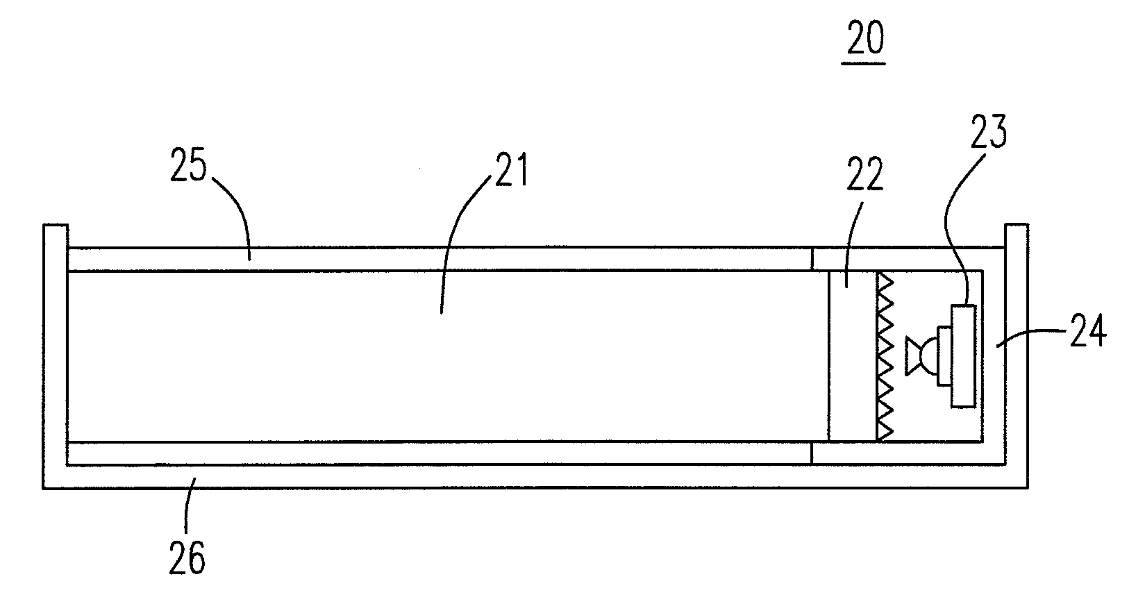
[0026]In order to more clearly understand the above objectives, features and advantages of the present invention, the following preferred embodiments in accordance with the appended figures of the present invention will be more clearly explained as follows:

[0027]Please refer to FI...


PUM


Abstract

A backlight module includes a light guide, a mixing light guide plate, and a plurality of light sources. The first light guide comprises a first side surface. The mixing light guide plate comprises an incident surface with anomalous surface and an emergent surface with fog surface. The mixing light guide plate is set on the first side surface. A plurality of light sources disposed corresponding to the incident surface, with light emitted there from and entering the mixing light guide plate through the incident surface then exits the mixing light guide plate through the emergent surface, finally, entering the light guide through the first side surface.

Description

FIELD OF THE INVENTION[0001]The present invention mainly relates to a backlight module, particularly to a backlight module applied in a liquid crystal display device.BACKGROUND OF THE INVENTION[0002]In recent years, the products using the liquid crystal display (LCD) has become very popular, such as notebook computers, monitors, mobile phones cameras, LCD TVs, digital cameras and personal digital assistants (PDA), etc. Their applications can be easily found everywhere. Since the LCD cannot luminesce itself, the function of the backlight module is to provide the light source, which can provide sufficient brightness and uniform light distribution on the LCD panel. Therefore, the backlight module is actually inevitable equipment for the LCD products. Furthermore, the backlight module will still be a suitable choice in the other applied field of luminescent requirement even if it is not applied to the LCD products.[0003]Traditionally, liquid crystal displays use the Cold Cathode Fluores...

Claims


Application Information

Patent Timeline
Patent Type & Authority Patents(United States)
IPC IPC(8): F21V7/04
CPCG02B6/0025G02B6/0028G02B6/0068
Inventor CHANG, CHIH-LI
Owner HANNSTAR DISPLAY CORPORATION
Why Eureka
Try Eureka