Real-time pixel substitution for thermal imaging systems

a technology of thermal imaging and real-time pixel substitution, applied in the field of imaging systems, can solve the problems of large deficiency in subjective image quality, small portion of these pixels may degrade, and unit being returned for repair at significant cost to either the customer or the supplier, so as to suppress the expression of a defective pixel, prevent these degraded pixels, and eliminate distractions

Active Publication Date: 2012-07-24
BAE SYST INFORMATION & ELECTRONICS SYST INTERGRATION INC
View PDF14 Cites 2 Cited by
  • Summary
  • Abstract
  • Description
  • Claims
  • Application Information

AI Technical Summary

Benefits of technology

[0005]According to the present invention, the non-uniformity correction (NUC) process for imaging engines has been augmented with real-time pixel substitution capability. This feature checks for pixels that have significantly degraded from their factory performance. Degraded pixels found are first identified and then substituted in real time. The substitution is implemented by discarding the value read from the degraded pixel and substituting a value derived from good pixels in the vicinity of the degraded one. This process eliminates distractions to the camera system operator and prevents these degraded pixels from degrading the subjective image quality. The process of identifying a degraded pixel and substituting a new pixel value for the value read from it is referred to within as ‘killing’ a pixel. That is, to suppress the expression of a defective pixel by replacing its value with one derived from other, good pixels. Similarly, “bad pixel” or “good pixel” refers to the value attributed to a pixel identified as meeting criteria for a “bad” or “good” pixel, respectively. Additionally, pixel substitution refers to substituting the value read from a bad pixel with a value derived from neighboring good pixels.

Problems solved by technology

A small portion of these pixels may degrade during the lifetime of the system, which is a significant deficiency to the subjective image quality and a distraction to the operators of the camera system.
Often, these will result in a unit being returned for repair at significant cost to either the customer or the supplier.

Method used


Image

  • Real-time pixel substitution for thermal imaging systems
  • Real-time pixel substitution for thermal imaging systems
  • Real-time pixel substitution for thermal imaging systems

Examples


example 1

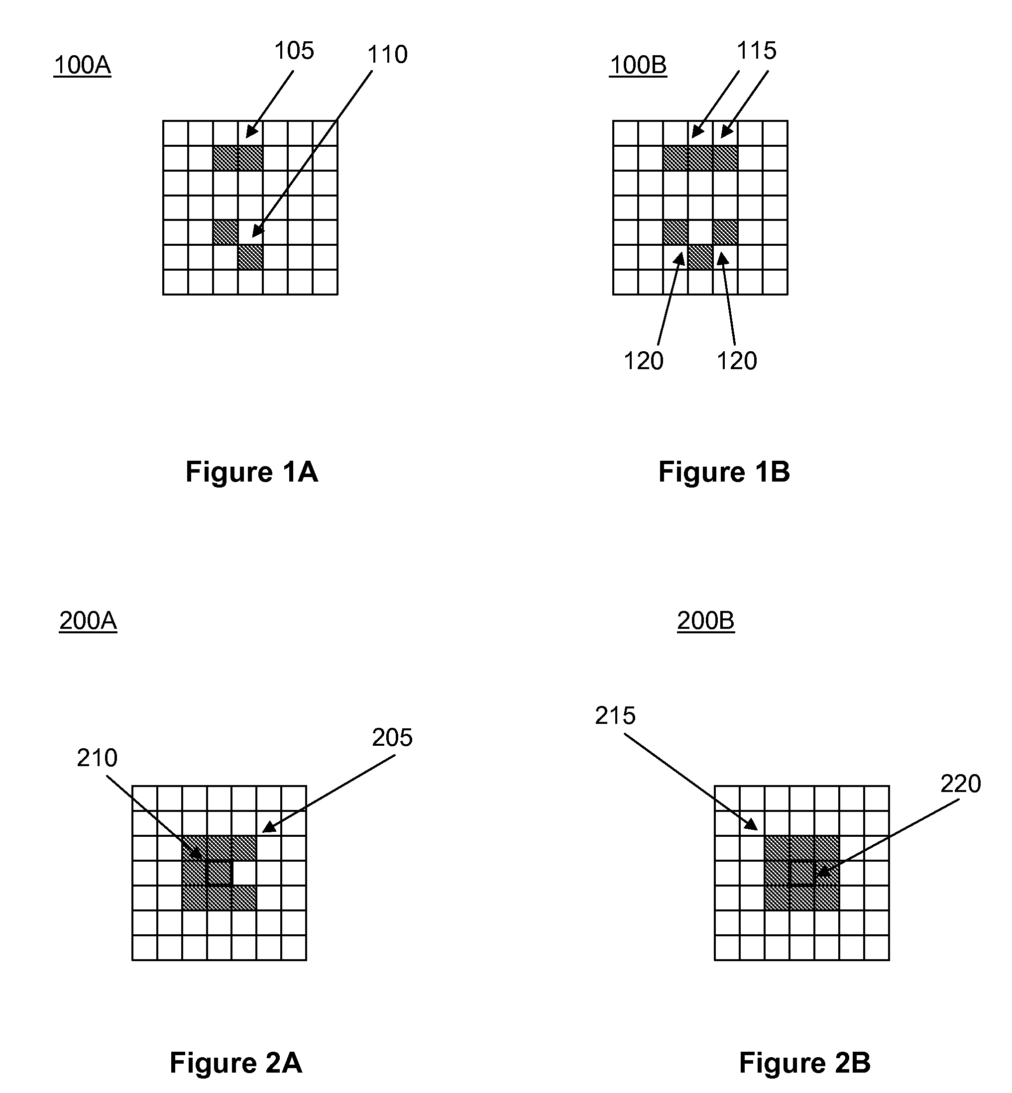
[0032]Referring to FIGS. 2A and 2B, the center pixel 210, and center pixel 220 each is only classified as a cluster, since in each case it is adjacent to less than two good pixels. The remaining seven pixels 205, or eight pixels 215 (around the border) would only count against the total number of bad pixels.

example 2

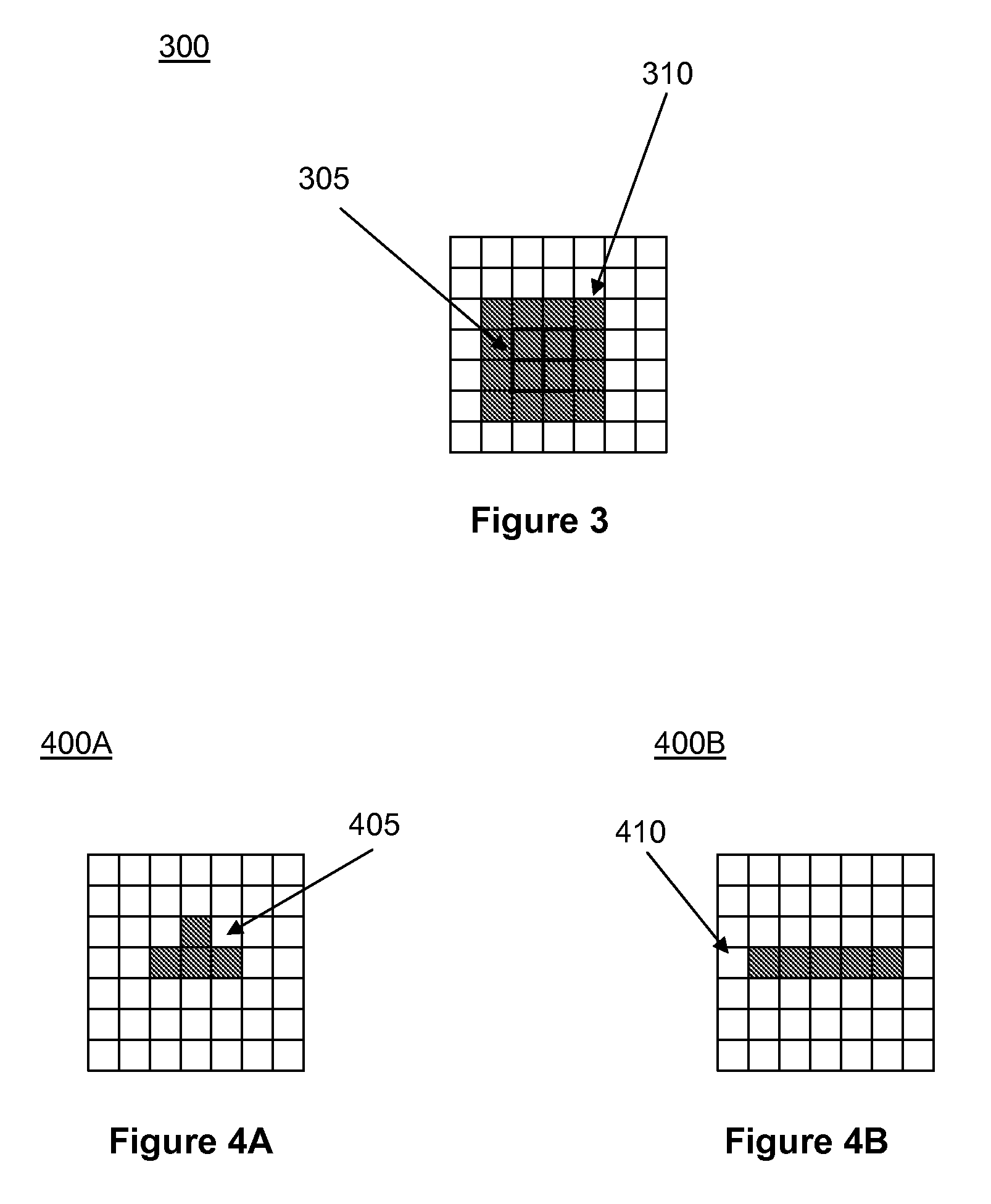
[0033]Referring to FIG. 3, the four pixels 305 in the center are each considered a bad cluster, since none of them is adjacent to at least two good pixels. Thus, the four pixels 305 in the center would add four to the total number of clusters found in this region of the image. The remaining pixels 310 (around the border) would count against the total number of bad pixels only. Other arrangements of bad pixels not meeting the rules identified above would be classified only as bad pixels, counted against the area in which they fall.

example 3

[0034]Referring to FIGS. 4A and 4B, these groupings of pixels are not considered pairs or clusters since they meet neither definition. In this case, the bad pixels count against the total number of bad pixels in the area. If an area boundary cuts through a grouping of pixels, then the bad pixel count statistics are updated based on the number of bad pixels that fall into each area.

[0035]Operability requirements can be defined by certain features and rules. The following nine features and rules are described next.

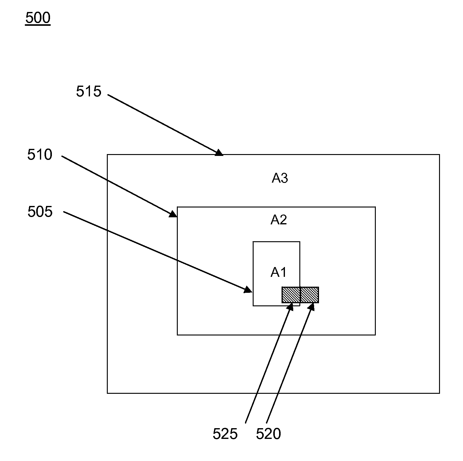
[0036]Feature 1. Referring to the embodiment of FIG. 5, there shall be a maximum of three image areas as shown in the following figure. Each region shall be treated independently. That is, area A1 shall not be considered to be included in A2. Neither shall A1 nor A2 be considered included in A3 in this embodiment. The number, size and location of the image areas A1, A2, and A3 should be considered exemplary only as well as the fact that they should be treated independently. ...


PUM


Abstract

A non-uniformity correction (NUC) process for imaging engines is augmented with real-time pixel substitution capability. This feature checks for pixels that have significantly degraded from their factory performance. Degraded pixels found are then substituted in real time. This process eliminates distractions to the camera system operator and prevents these degraded pixels from degrading the subjective image quality.

Description

RELATED APPLICATIONS[0001]This application claims the benefit of U.S. Provisional Application No. 60 / 880,586, filed Jan. 16, 2007. This application is herein incorporated in its entirety by reference.FIELD OF THE INVENTION[0002]The invention relates to imaging systems and, in embodiments, to pixel substitution in imaging and cooled and uncooled thermal imaging systems.BACKGROUND OF THE INVENTION[0003]Camera systems, including cooled and uncooled thermal imaging systems, developed to date are focal plane based with 20,000 to 300,000 pixels. A small portion of these pixels may degrade during the lifetime of the system, which is a significant deficiency to the subjective image quality and a distraction to the operators of the camera system. Often, these will result in a unit being returned for repair at significant cost to either the customer or the supplier.[0004]What is needed, therefore, are techniques to overcome this disadvantage.SUMMARY OF THE INVENTION[0005]According to the pres...

Claims


Application Information

Patent Timeline
Patent Type & Authority Patents(United States)
IPC IPC(8): H04N9/64H04N5/217
CPCH04N5/2176H04N5/3675H04N5/33H04N25/63H04N25/683
Inventor LIBERMAN, SERGEYFEDA, FRANCIS M
Owner BAE SYST INFORMATION & ELECTRONICS SYST INTERGRATION INC
Why Eureka
Try Eureka