Method and system for riserless casing seat optimization

a technology of casing seat and optimization method, which is applied in the direction of seismology for waterlogging, instruments, borehole/well accessories, etc., can solve the problems of not providing enough leakage tolerance, little strength or competency, and the placement of the casing seat, so as to improve the leakage tolerance, improve the effect of casing seat optimization and mitigate shallow drilling hazards

Active Publication Date: 2012-07-24
PRITCHARD DAVID M +1
View PDF12 Cites 3 Cited by
  • Summary
  • Abstract
  • Description
  • Claims
  • Application Information

AI Technical Summary

Benefits of technology

[0008]The present invention provides a system and method of optimizing casing seats for riserless deepwater oil and natural gas drilling of hole sections and corresponding stings of casings by providing a design system and methodology for optimum casing set placement. The well design system and method of the present invention effectively takes advantage of the shallow and rapid growth of the fracture gradient in the subsea environment to optimize casing seats and shallow hazard mitigation and therefore improves leak-off tolerances for each successive casing string which allows for fewer and larger diameter casing strings than in a conventional deepwater well. In operation, the method and system of the present invention employs the use of common oilfield tubular diameters to attain well true vertical depth, allows for more conventional hole diameters for mechanical and geological side-tracks, a final well diameter that is optimized for field development flow rates, limiting failure hazards, allowing for the attainment of well objectives and well field development economic objectives.

Problems solved by technology

The current approach of “jetting” in the first string of casing, usually 250 to 350 ft below the mud line, results in a casing seat being placed too shallow thereby not providing enough leak-off tolerance for the drilling of the next hole section.
This is due to the very soft formations which have little strength or competency for fracture resistance and leak-off.
The general intended purpose of the structural string is limited to supporting the weight of subsequent casing strings and wellhead, and the resistance of bending moment of the riser loading.
Despite this perception, in reality, the structural string's ability to support much of an axial load is limited and thus can become a structural failure hazard if there is not enough soil bearing strength for the landing of the subsequent strength of casing and wellhead.
The conventional approach adds little to the value of the well design, since this casing setting depth does not supply sufficient axial loading resistance for structural support of subsequent deeper casing strings nor does it supply sufficient bending load or sufficient rising bending moment.
Also, there is no value related to the growth of the fracture gradient in the first string and that negatively impacts the overall well design by wasting casing diameters.
Because the conventional placement of the casing well above every anticipated drilling hazard, such placement negatively impacts the casing diameters and hole sizes for well depths that routinely exceed 30,000 ft in measured depth.
As is understood in the art, deepwater oil drilling is an expensive and time intensive venture.
Daily operating costs often approach $1,000,000.00 requiring 100 days or more to drill before achieving the well objectives.
The complex deepwater drilling environments have pushed well design to its limits and while many of the aspects of deepwater drilling and well design are being optimized, the optimal placement of the first and subsequent casing seats have been overlooked.

Method used


Image

  • Method and system for riserless casing seat optimization
  • Method and system for riserless casing seat optimization
  • Method and system for riserless casing seat optimization

Examples


Embodiment Construction

[0024]The description herein is given by way of example, and not limitation. Given the disclosure herein, one skilled in the art could devise variations that are within the scope and spirit of the invention disclosed herein, including various ways of calculating optimal depth data or casing seat placement. Further, the various features of the embodiments disclosed herein can be used alone, or in varying combinations with each other and are not intended to be limited to the specific combination described herein. Thus, the scope of the claims is not to be limited by the illustrated embodiments.

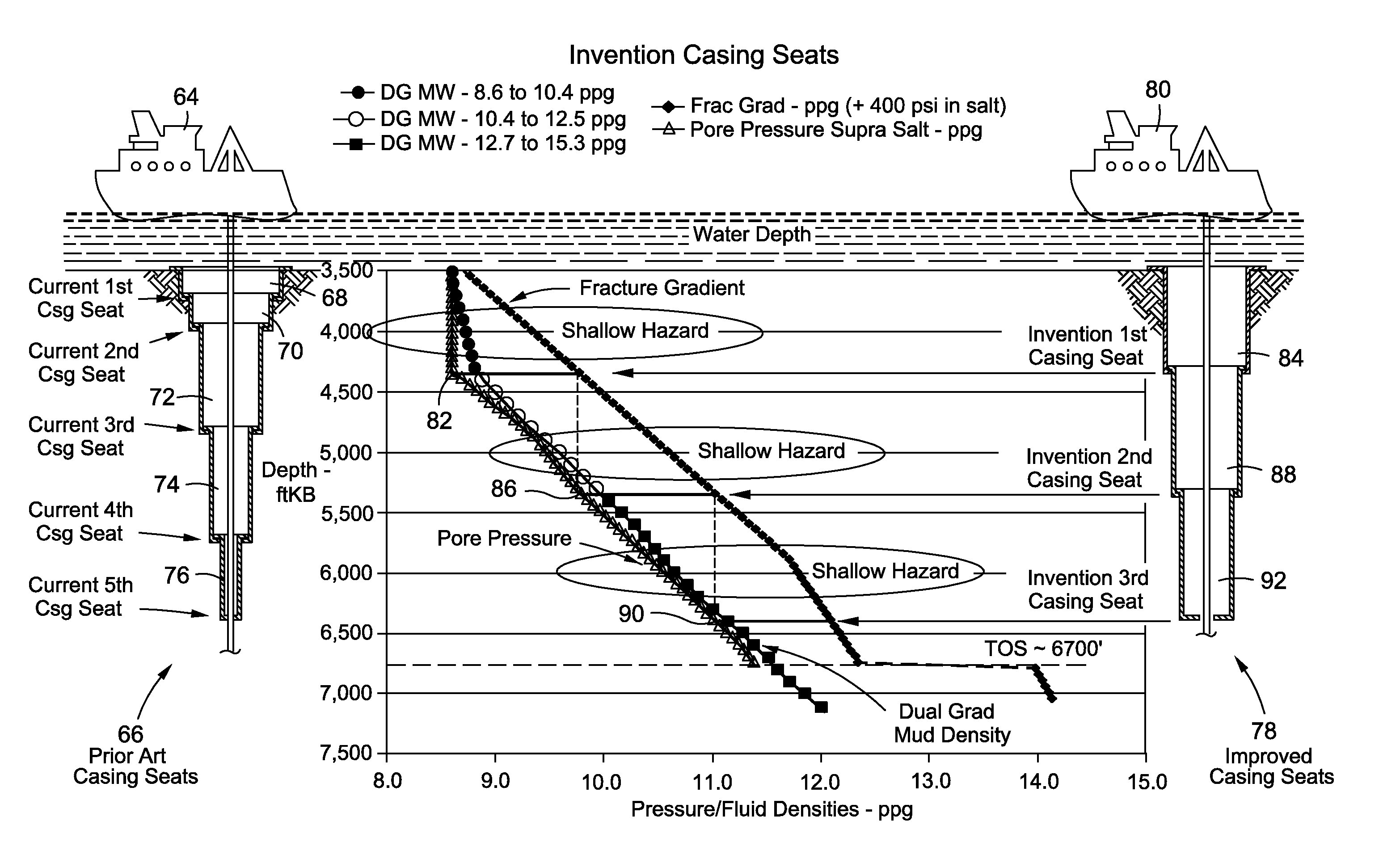
[0025]The present invention relates to a system and method for the optimum placement of drilling casing strings in deepwater drilling environments. The present invention uses a computer for processing and calculating the data necessary to optimize the placement of the casing strings as described herein. In operation, the code used to execute the data collection and computation may be preferably ...


PUM


Abstract

A system and method for optimal placement of a riserless casing in a subsea drilling environment having the steps of: receiving input of pore pressure data for a well site; receiving input of fracture gradient for said well site; receiving input of the anticipated true vertical depth of said well site; integrating pore pressure data, fracture gradient data with said true vertical depth values; computing a pore pressure and fracture gradient verses true vertical depth graph; determining the true vertical depth at which the pore pressure begins to exceed the normal gradient of salt water; and determining the placement of a conductor casing string by corresponding the gradient true vertical depth to the true vertical depth of where the pore pressure beings to exceed the normal gradient of salt water. The method improves upon conventional placement of the riserless casing by optimizing the placement to achieve larger diameters in the wellbore, increased well depth, and mitigation of shallow hazards. Furthermore, the method of the present invention transforms readily available data to calculate optimal placement of a structural casing string to serve a dual purpose by providing not only structural integrity for the wellbore, but also ensuring leak-off integrity by taking advantage of the early growth of the fracture gradient of the natural subsea environment. Also, the suggestion that casing drilling will assist in mitigating shallow drilling hazards to allow casing seats to be placed as prescribed by this present invention. The method of the present invention may be implemented by a computer based apparatus or implemented using executable computer code on a computer based system.

Description

CROSS-REFERENCE TO RELATED APPLICATIONS[0001]This application claims the benefits of provisional patent application Ser. No. 61 / 233,765 filed on Aug. 13, 2009, the entire contents of which is incorporated herein by reference. This application also claims the benefits of provisional patent application Ser. No. 61 / 243,079 filed on Sep. 16, 2009, the entire contents of which is incorporated herein by reference.STATEMENT RE: FEDERALLY SPONSORED RESEARCH / DEVELOPMENT[0002]Not ApplicableBACKGROUND[0003]The present invention relates generally to a system and method for optimizing riserless drilling casing seats used in offshore deepwater drilling from a floating platform. More particularly, the present invention uses a system and method for determining the optimal placement of the initial casing seats by using, among other criteria, the relationship between the pore pressures and fracture pressures to determine a depth that will optimize placement of riserless casing seats to achieve deeper...

Claims


Application Information

Patent Timeline
Patent Type & Authority Patents(United States)
IPC IPC(8): G01V1/40
CPCE21B21/08
Inventor PRITCHARD, DAVID M.KOTOW, KENNETH J.
Owner PRITCHARD DAVID M
Why Eureka
Try Eureka