Reel structure for marine fabric tape

a fabric tape and reel structure technology, applied in the direction of thin material handling, lifting devices, wire tools, etc., can solve the problems of looseness, damage, difficulty, etc., and achieve the effect of prolonging the service li

Inactive Publication Date: 2012-07-31
PENG I SIN
View PDF16 Cites 19 Cited by
  • Summary
  • Abstract
  • Description
  • Claims
  • Application Information

AI Technical Summary

Benefits of technology

[0006]The head portion of the fabric tap is inserted through the slot into the pivotal hole, and the axle bolt is inserted through one of the pair of axle holes of the base, the pivotal hole of the gear tray, the head portion, and the other axle hole in sequence so that the gear tray is connected to the base. The gear disc meshes with the teeth of the gear shaft. The stop plate is urged by the straight torsion spring such that the stop portion engages with the teeth of the gear shaft to prevent a reverse rotation. When the handle of the windlass is rotated, the flat rod will be driven to rotate the gear shaft which then drives the gear disc tray to rotate. Because the head portion is positioned in the axle shaft, the fabric tape is rolled up along with the axle shaft to from a circular shape. The user can roll up the fabric tape repeatedly with the same force. The axle shaft functions as an axle center to roll up or to release the fabric tape in the form of a circle, thus its structure bears the same stress direction. It is not easy to have breakdown points in different directions which may cause looseness or damage. The present invention provides a longer service life.

Problems solved by technology

It is not easy to have breakdown points in different directions which may cause looseness or damage.

Method used


Image

  • Reel structure for marine fabric tape
  • Reel structure for marine fabric tape
  • Reel structure for marine fabric tape

Examples


Embodiment Construction

[0015]Embodiments of the present invention will now be described, by way of example only, with reference to the accompanying drawings.

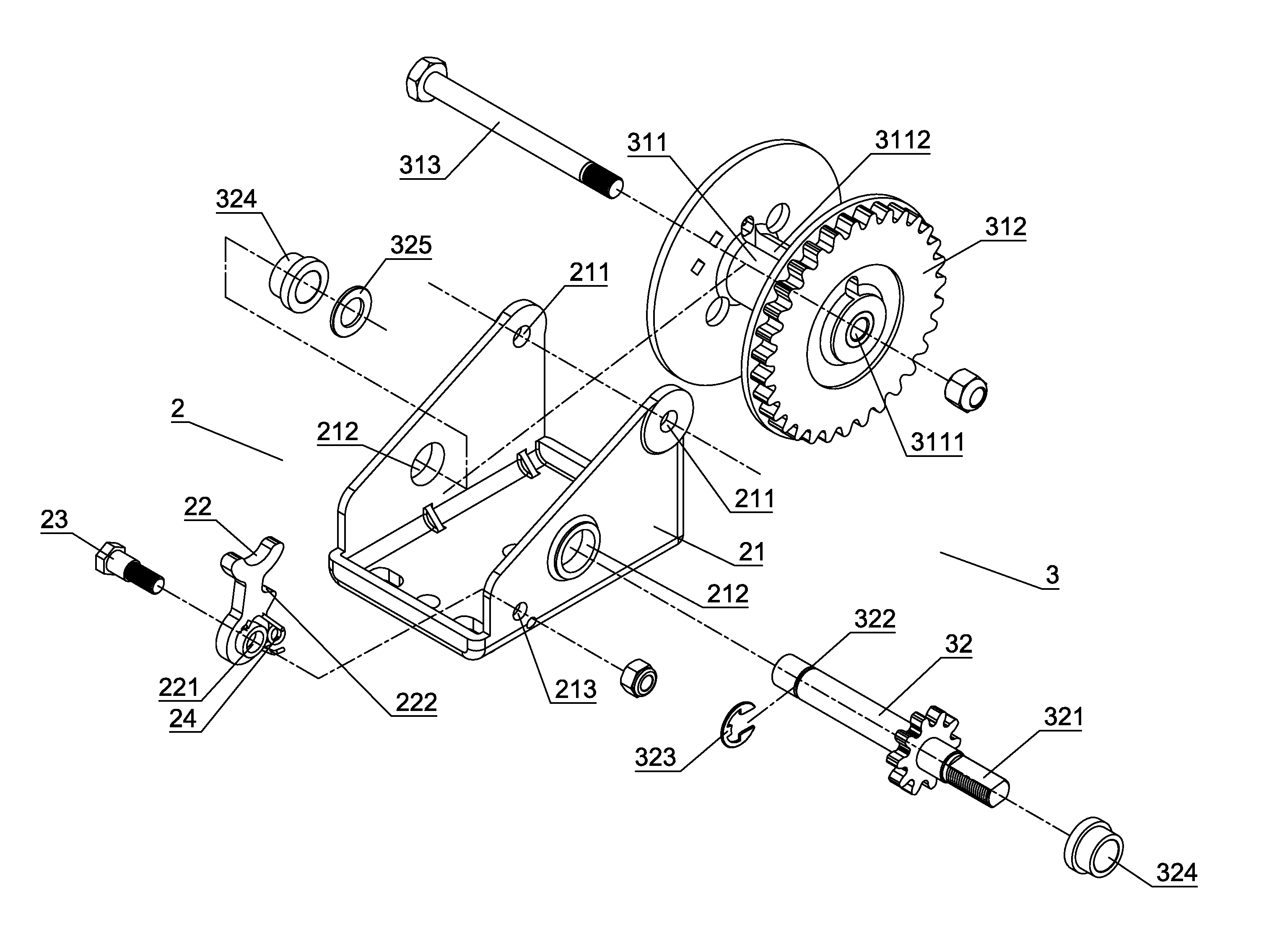
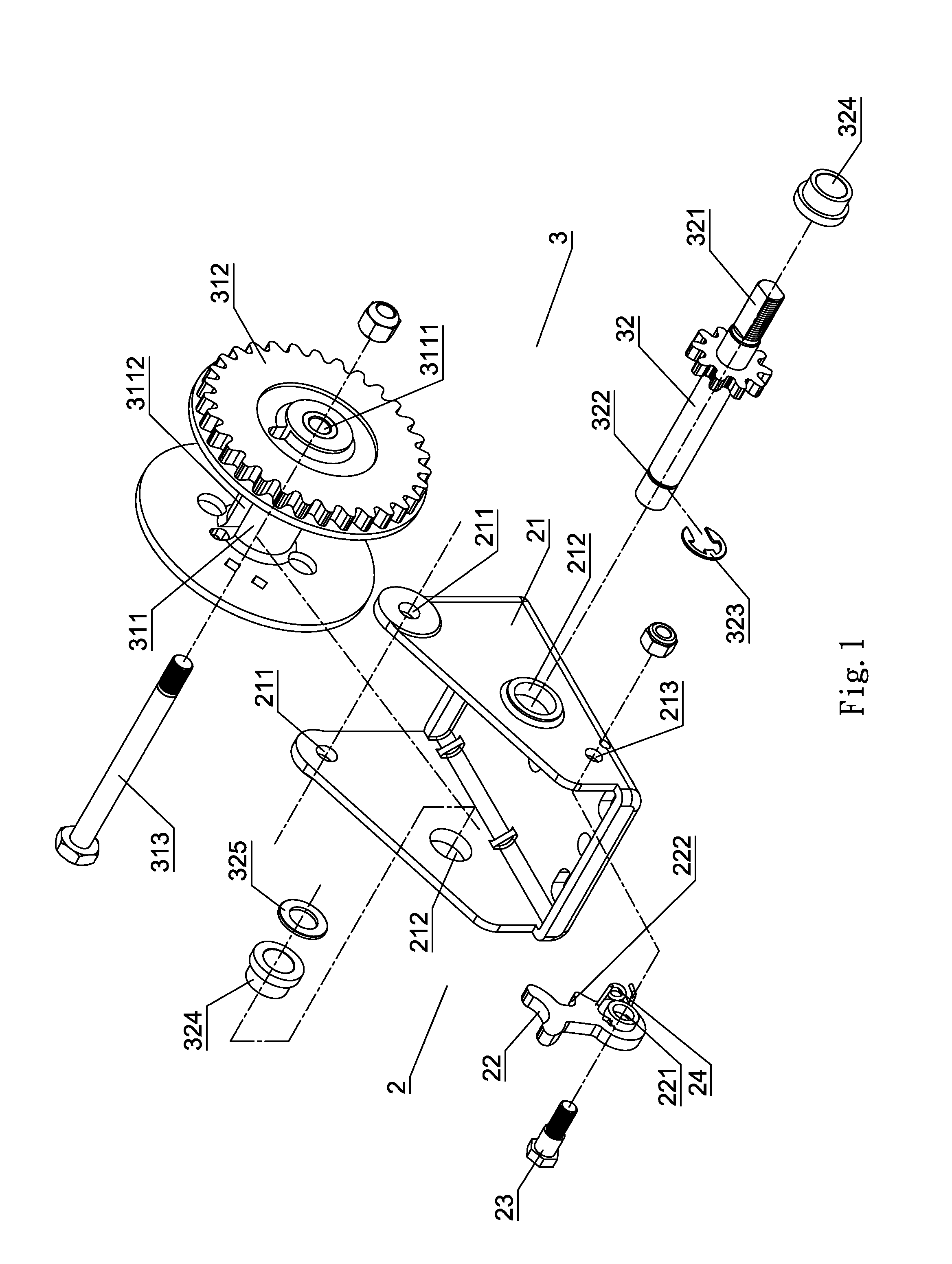
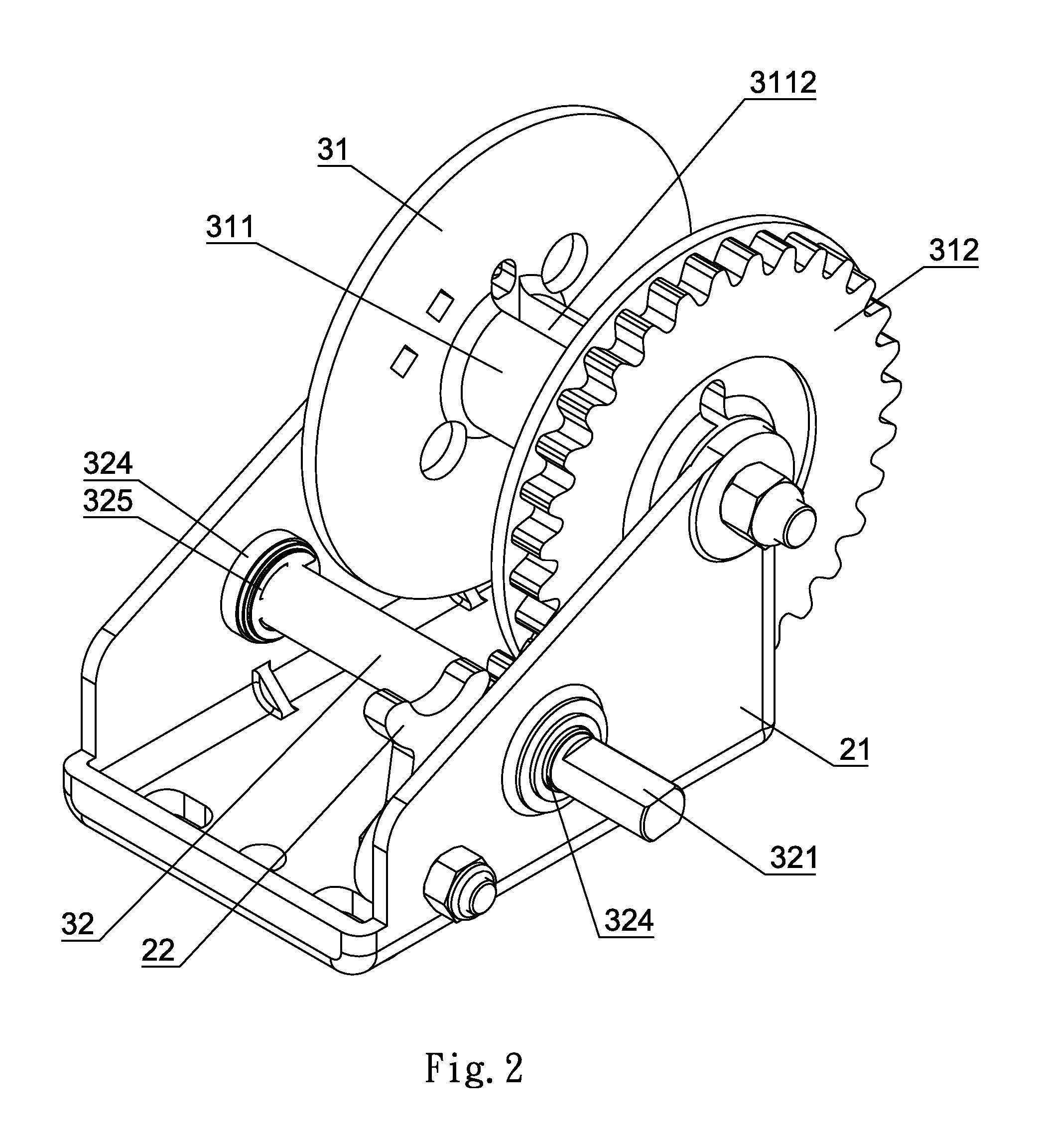
[0016]As shown in FIGS. 1 and 2, the present invention comprises an engaging seat 2 and a reel device 3 which is pivotally connected to the engaging seat 2.

[0017]The engaging seat 2 comprises a base 21, a stop plate 22, a positioning bolt 23, and a straight torsion spring 24. The base 21 has two side boards formed with a pair of axle holes 211 and a pair of rotation holes 212. One of the two side boards is formed with an aperture 213 which is disposed in front of the relative rotation hole 212. The positioning bolt 23 is inserted through a positioning hole 221 of the stop plate 22 and the aperture 213 to be secured inside the engaging seat 2. The straight torsion spring 24 is mounted on a lower portion of the stop plate 22 for a stop portion 222 of the stop plate 22 to engage with teeth of a gear shaft 32 so as to prevent disengagement due to a revers...


PUM

PropertyMeasurementUnit
forceaaaaaaaaaa
applied forceaaaaaaaaaa
stressaaaaaaaaaa

Abstract

A reel structure for a marine fabric tape includes a reel device pivoted to an engaging seat. When a handle of a windlass is turned, a flat rod will be driven to rotate a gear shaft which then drives a gear disc to rotate. Because a head portion is positioned in an axle shaft, a fabric tape is rolled up along with the axle shaft to form a circular shape, providing an even applied force for rolling up the fabric tape.

Description

BACKGROUND OF THE INVENTION[0001]1. Field of the Invention[0002]The present invention relates to a reel structure for a marine fabric tape, and more particularly to one having a head portion in a water drop shape of the fabric tap to be positioned in an axle shaft of a gear tray for rolling up the fabric tap along with the axle shaft, providing an even applied force.[0003]2. Description of the Prior Art[0004]As shown in FIG. 5 and FIG. 5-A, a conventional reel structure for a marine fabric tape comprises a gear tray 31′ having a central axle shaft 311′ and an axle bolt 313′ which is located apart from the axle shaft 311′. The axle bolt 313′ is inserted through the gear tray 31′ and a head portion A1 of a fabric tape A. The head portion A1 is in a water drop shape. With a handle of a windlass to turn the axle shaft, the gear tray 31′ is driven to rotate. Because the head portion A1 of the fabric tape A is positioned on the axle bolt 313′, the fabric tape A first wraps the axle shaft ...

Claims


Application Information

Patent Timeline
Patent Type & Authority Patents(United States)
IPC IPC(8): B21F9/00
CPCB65H75/28B65H75/4431B65H2701/37B65H2701/537
Inventor PENG, I-SIN
Owner PENG I SIN
Why Eureka
Try Eureka