Bone reduction and plate clamp assembly

a technology of plate clamping and bone reduction, which is applied in the field of bone reduction and plate clamping assembly, can solve the problems of not revealing the same or similar elements, not presenting the material components in a manner, and the base member failing to disclose the attachment to any alignment bar

Inactive Publication Date: 2012-07-31
JORDAN CHRISTOPHER
View PDF11 Cites 85 Cited by
  • Summary
  • Abstract
  • Description
  • Claims
  • Application Information

AI Technical Summary

Benefits of technology

[0009]During a surgical reduction of a displaced fracture of a bone, human or other animal, the bone must be aligned and stabilized for the application of a surgical plate using surgical screws to secure the bone fracture together to allow it to heal in proper alignment. A surgeon must manually manipulate the bone section into a proper alignment and then either hold the bones together to apply the plate in place or use the hands of several other assistants to perform the maneuvers required during the surgical repair process.

Problems solved by technology

However, the prior art inventions do not disclose the same or similar elements as the present bone reduction and plate clamp assembly, nor do they present the material components in a manner contemplated or anticipated in the prior art.
However the base member fails to disclose attachment to any alignment bar.
It also lacks any secondary means to position a bone plate between the clamp and the bone once the bone is secured.
This linear adjustment does not provide for a pivotally adjusted assembly nor does it disclose at least one pivotal means of allowing for the alignment bar to provide anything but a two-dimensional alignment of the bar and the clamps.

Method used


Image

  • Bone reduction and plate clamp assembly
  • Bone reduction and plate clamp assembly
  • Bone reduction and plate clamp assembly

Examples


Embodiment Construction

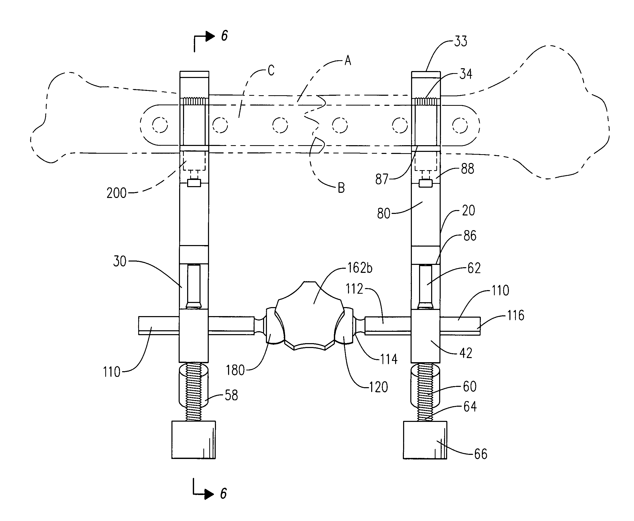
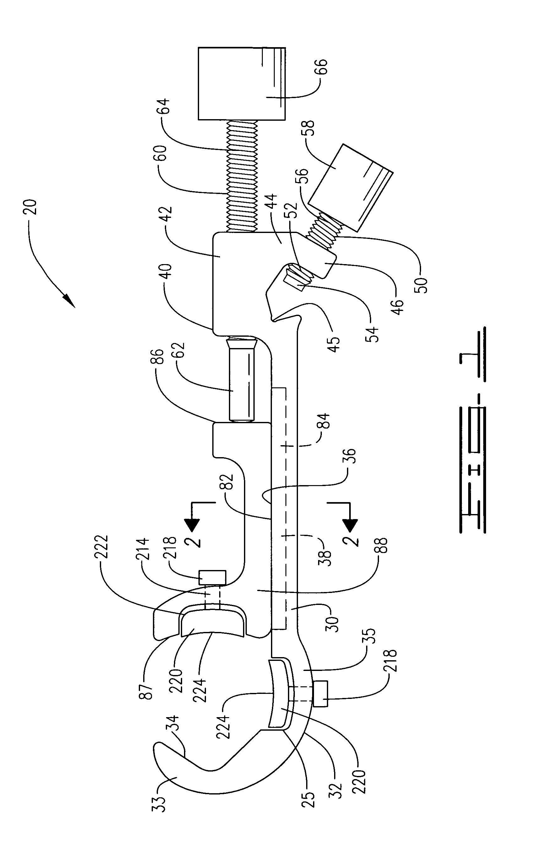
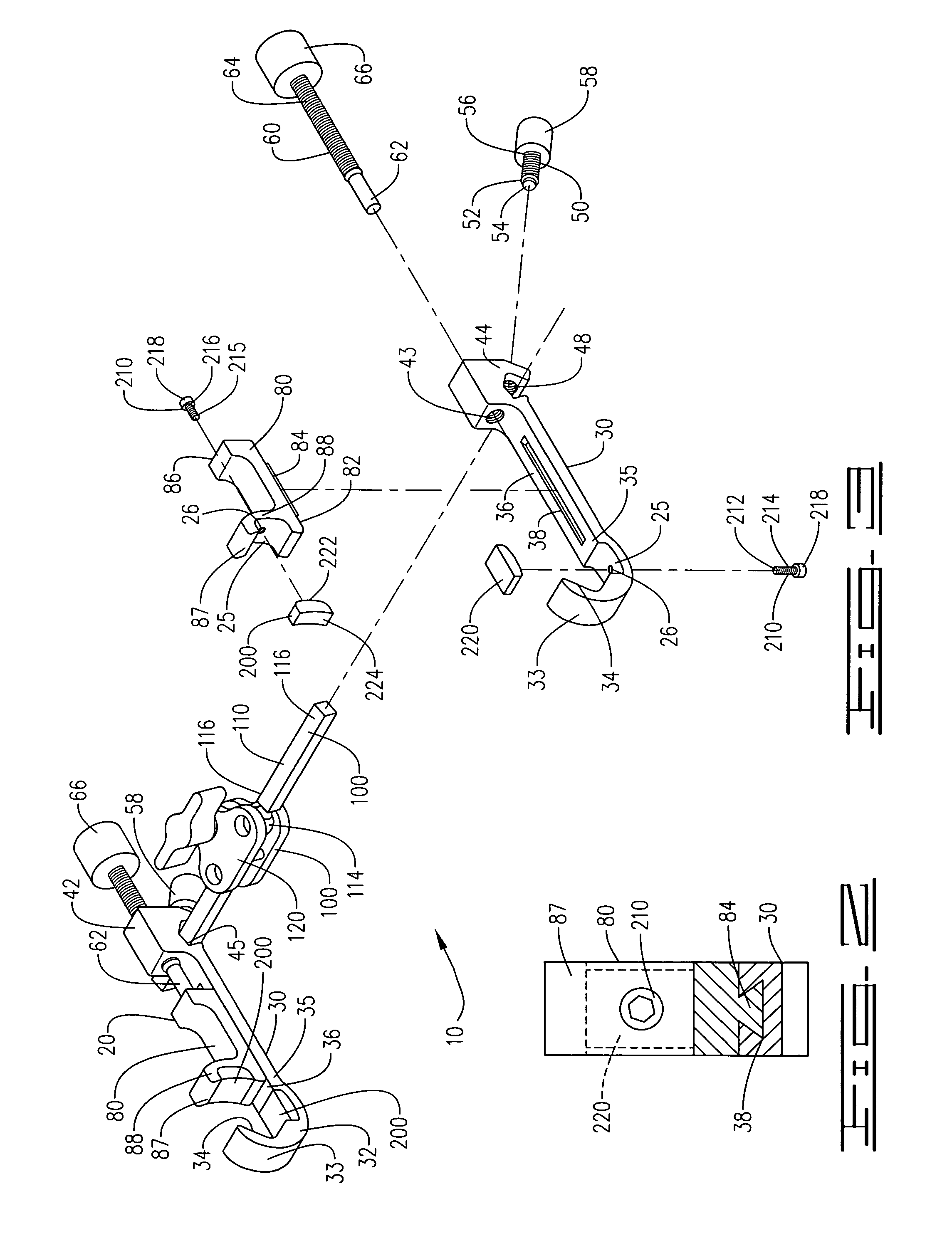
[0020]A linear bone clamp assembly 10, shown in FIGS. 1-7B of the drawings, comprises a pair of linear bone clamps 20 and a pivotal alignment bar 100, each linear bone clamp 20 attaching to a fractured bone A during a surgical repair of the bone, one on each side of the fracture site B, with each clamp 20 being further attached to the pivotal alignment bar 100 to reduce the fracture site and properly align the bone, with a bone plate C being inserted between each clamp 20 and its respective bone location, to secure the plate C to the bone A to stabilize the bone fracture site B for complete healing.

[0021]Each linear bone clamp 20, FIGS. 1-6, provides a base clamp member 30 having a first end 32 defining a first clamp plate 33 having an inner V-shaped clamping margin 34, a neck portion 35 providing an upper margin 36 defining a linear channel 38, and a second end 40 defining a base 42 having a central linear inner threaded bore 43 and an upper extension 44 defining a transverse bar r...


PUM


Abstract

A pair of clamps are attached to a damaged bone one each side of a fracture site during a surgical reduction, one clamp on each side of the fracture site, after which the two clamps are slidably engaged to a single pivotal alignment bar, with the clamps then being adjusted to properly align the bone for a surgical attachment using a bone plate which is secured between the respective bone and each respective clamp, holding the bone in place with the bone in proper alignment for the attachment of screws through the plate into the bone, stabilizing the fracture site during the plate attachment procedure.

Description

CROSS REFERENCE TO RELATED APPLICATIONS[0001]This Application claims the benefit of Provisional Patent Application No. 61 / 281,846 filed on Nov. 23, 2009, by the same inventor, Christopher Jordan.I. BACKGROUND OF INVENTION[0002]1. Field of the Invention[0003]A pair of clamps are attached to a damaged bone one each side of a fracture site during a surgical reduction, one clamp on each side of the fracture site, after which the two clamps are slidably engaged to a single pivotal alignment bar, with the clamps then being adjusted to properly align the bone for a surgical attachment using a bone plate which is secured between the respective bone and each respective clamp, holding the bone in place with the bone in proper alignment for the attachment of screws through the plate into the bone, stabilizing the fracture site during the plate attachment procedure.[0004]2. Description of Prior Art[0005]A preliminary review of prior art patents was conducted by the applicant which reveal prior ...

Claims


Application Information

Patent Timeline
Patent Type & Authority Patents(United States)
IPC IPC(8): A61B17/00A61F4/00A61F5/04
CPCA61B17/64A61B17/80A61B17/8866
Inventor JORDAN, CHRISTOPHER
Owner JORDAN CHRISTOPHER
Why Eureka
Try Eureka