Auto injector

a technology of injector and injection needle, which is applied in the direction of injection needle, intravenous device, automatic syringe, etc., can solve the problems of user discomfort and discomfort in handling the device, and achieve the effects of reducing discomfort, facilitating patient penetration, and fast penetration

Active Publication Date: 2012-08-07
SHL MEDICAL AG
View PDF4 Cites 63 Cited by
  • Summary
  • Abstract
  • Description
  • Claims
  • Application Information

AI Technical Summary

Benefits of technology

[0015]The advantages with the present invention are several. Due to the collapsing holding member, a certain force needs to be applied to the needle shield when pressed against an injection site. The force required means a few advantages. On the one hand, if the injector for some reason hits or is pushed with a rather low force against something, there is a small risk that the needle is exposed in contrast with a needle shield that has no counter force or even a spring urging the needle shield into the extended position, since the force of a spring is lowest when in the uncompressed state. On the other hand, the force required before the collapsible holding means collapses provides a rather fast penetration when collapsing, facilitating the penetration for the patient. The fast penetration also reduces the discomfort of the first penetration of the needle.
[0016]Further, due to the rather fast movement during penetration, the subsequent injection will take place rather rapidly. In all a fast and automatic injection process is obtained. The collapsing thus minimizes the risk that the patient will stop the penetration or hesitate, because this is done in a swift movement.
[0017]Since the injection device according to the invention preferably is a disposable device, the collapsible holding member is a cost-effective part because it comprises few components that still are capable of performing the desired function. The collapsible member could be made of metal or plastic bands or strips of low cost. Even if it is made as a tubular member, it is cost-effective since the strips then are formed by cutting out longitudinal parts.
[0018]Further, the bands or strips have a curved or V-shaped form in cross-section to provide a certain stability or stiffness. It is of course conceivable to have other cross-sectional shapes, such as oval, zig-zag, S-shaped etc. which provide the required stability. The shapes could be modified in order to set different force levels required before the collapsible holding member actually collapses. For example, for persons with weak hands and arms, such as persons having rheumatism, the shapes could be chosen such that a lower force is required.
[0019]Regarding persons having difficulties holding the device for injection, such as rheumatics, it is an advantage that the housing is provided with enlargements for accommodating the collapsed holding member, where the enlargement enables a better grip and guide of the injector when using it.

Problems solved by technology

For many patients using injecting devices for self-administration of medicament, there is a discomfort to handle the device, especially regarding the penetration.
Also, when the needle is about to slowly penetrate human skin; there is a certain start resistance that can give the user discomfort.
This could be difficult when the injector has push buttons on the distal end of the injector or slide buttons on the side of the injector.

Method used


Image

  • Auto injector
  • Auto injector
  • Auto injector

Examples


Embodiment Construction

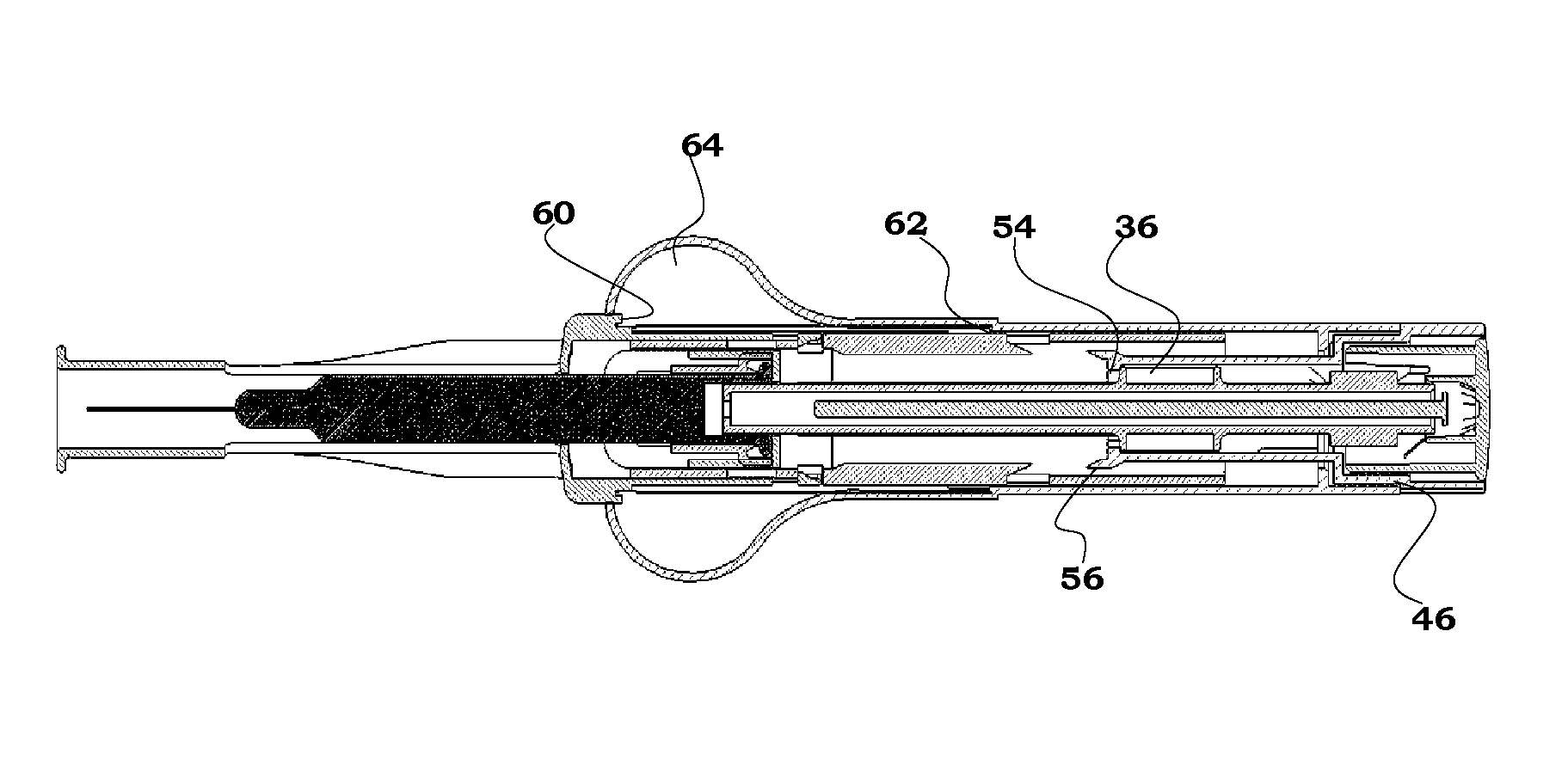
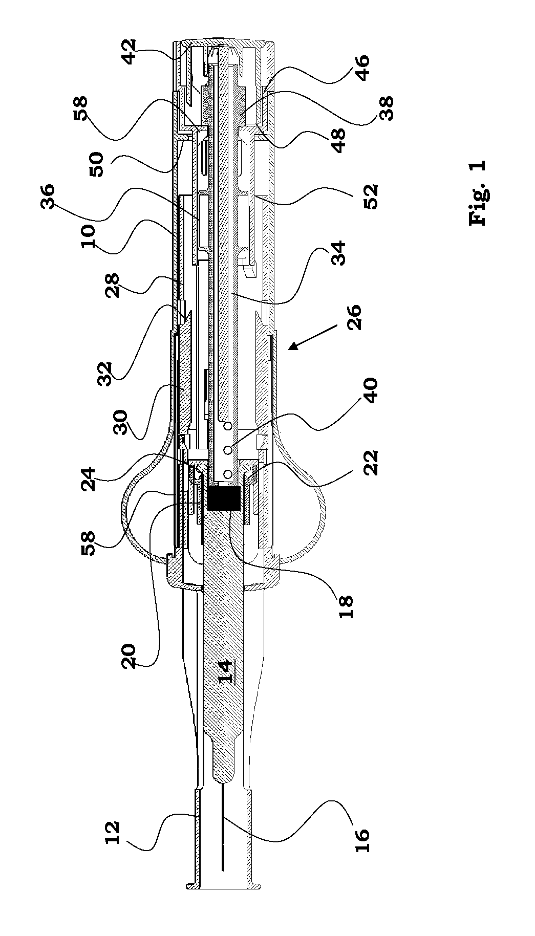
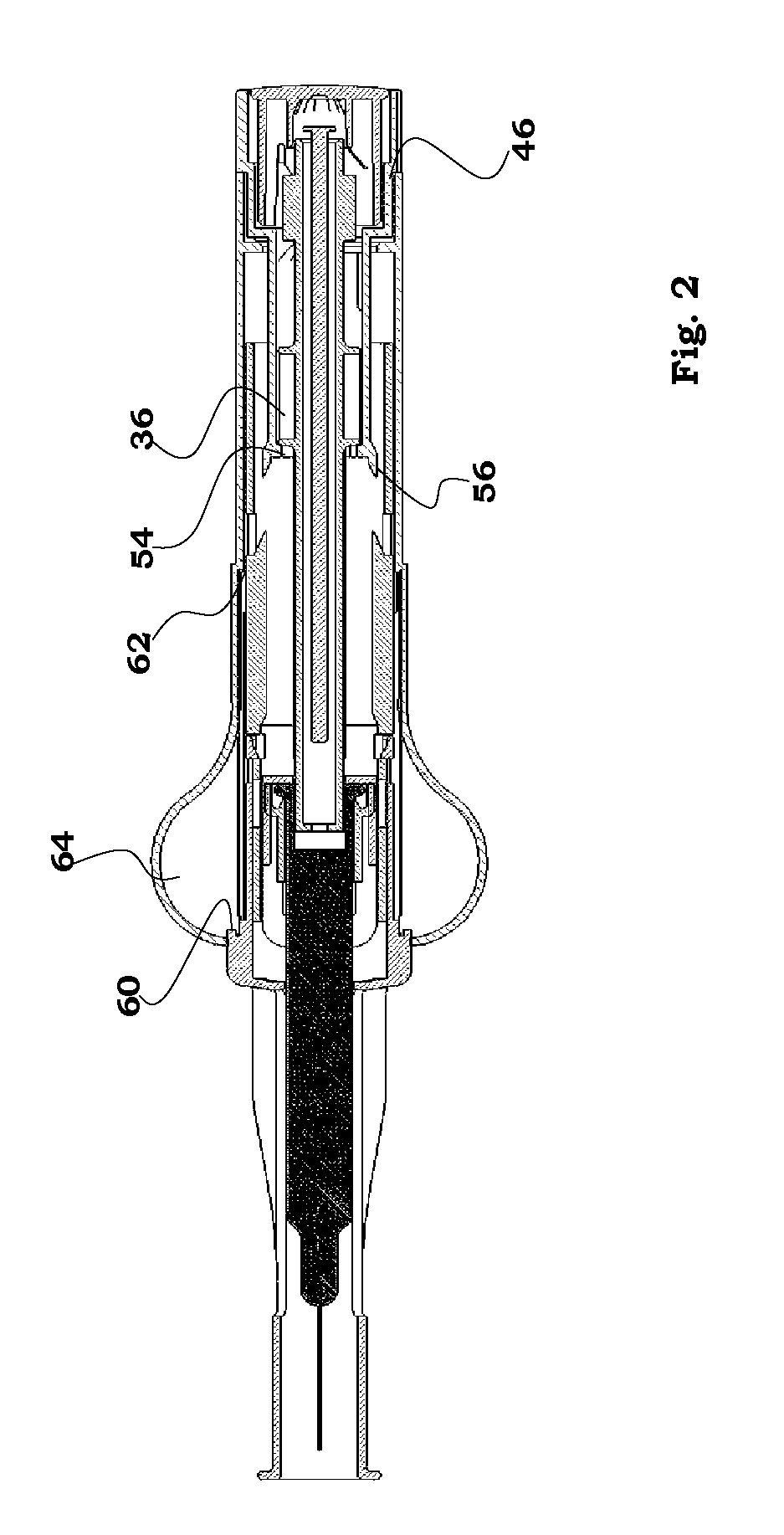
[0026]An embodiment of an injection device is shown in FIGS. 1, 2 and 3. It comprises a generally tubular elongated housing 10. At the front end of the housing, to the left in the figures, a needle shield 12 is arranged to be slidable in and out of the housing. Inside the needle shield and extending into the housing is a container 14, e.g. a cartridge, a syringe or the like, containing medicament to be injected. A needle 16 is attached to the front end of a cartridge. In the rear end of the container a stopper 18 is arranged. The rear end of the container is inserted into a container holder 20 provided with stop ledges 22 on which a circumferential ledge 24 is resting, for preventing movement of the container. The rear end of the needle shield, to the right in the figures, is in contact with an activating means 26, in the form of a generally tubular elongated member 28 extending into the interior of the housing. The activating means is arranged with inwardly extending longitudinal l...


PUM


Abstract

The present invention relates to a disposable injection device for delivering a dose of medicament, comprising a generally elongated housing (10), a container (14) containing medicament to be injected through a needle (16), force means (34) acting on said container and capable of, upon activation, move said container and said needle for penetration and subsequently expelling medicament through said needle, activating means (26) arranged to activate said force means, characterized in that said activating means comprises a needle shield (12) arranged slidable in relation to said housing, a collapsible holding member (58) connected to the inner end of said needle shield, whereby, upon movement of said needle shield, said collapsible holding member collapses when a certain force is applied by the needle shield, and whereby further movement of said needle shield activates said activation means, which in turn releases said force means initiating an injection of medicament.

Description

[0001]This is a national stage application of PCT application NO. PCT / EP08 / 51441, filed Feb. 6, 2008, which claims priority to Sweden Utility Application No. 0700801-4, filed Mar. 23, 2007, the contents of each of the foregoing are expressly incorporated herein by reference for all purposes.TECHNICAL FIELD[0002]The present invention relates to an auto-injector comprising needle shield activation of the penetration and subsequent injection.BACKGROUND ART[0003]For many patients using injecting devices for self-administration of medicament, there is a discomfort to handle the device, especially regarding the penetration. For many users there is a mental resistance against self-penetration. Other users also have a general fear of needles which enhances the discomfort and negative feeling of self-administration. Also, when the needle is about to slowly penetrate human skin; there is a certain start resistance that can give the user discomfort.[0004]It is further desirable for many patien...

Claims


Application Information

Patent Timeline
Patent Type & Authority Patents(United States)
IPC IPC(8): A61M5/32A61M5/00
CPCA61M5/2033A61M5/326A61M5/3287A61M2005/2013A61M2005/3267
Inventor WIKNER, JAKOB
Owner SHL MEDICAL AG
Why Eureka
Try Eureka