Control box arrangement

a technology of control box and box body, which is applied in the direction of revolving cabinets, electrical appliances, other domestic objects, etc., can solve the problems of difficult horizontal subdivide space, relatively complex connecting rails,

Active Publication Date: 2012-08-14
RITTALWERK RUDOLF LOH GMBH & CO KG
View PDF26 Cites 5 Cited by
  • Summary
  • Abstract
  • Description
  • Claims
  • Application Information

AI Technical Summary

Benefits of technology

[0006]One object of this invention is to provide a control box arrangement of the type mentioned above that ena

Problems solved by technology

This design provides simple possibilities for assembly and arrangement, but requires relatively complex connecting rails.
With this design, it is diff

Method used


Image

  • Control box arrangement
  • Control box arrangement
  • Control box arrangement

Examples


Embodiment Construction

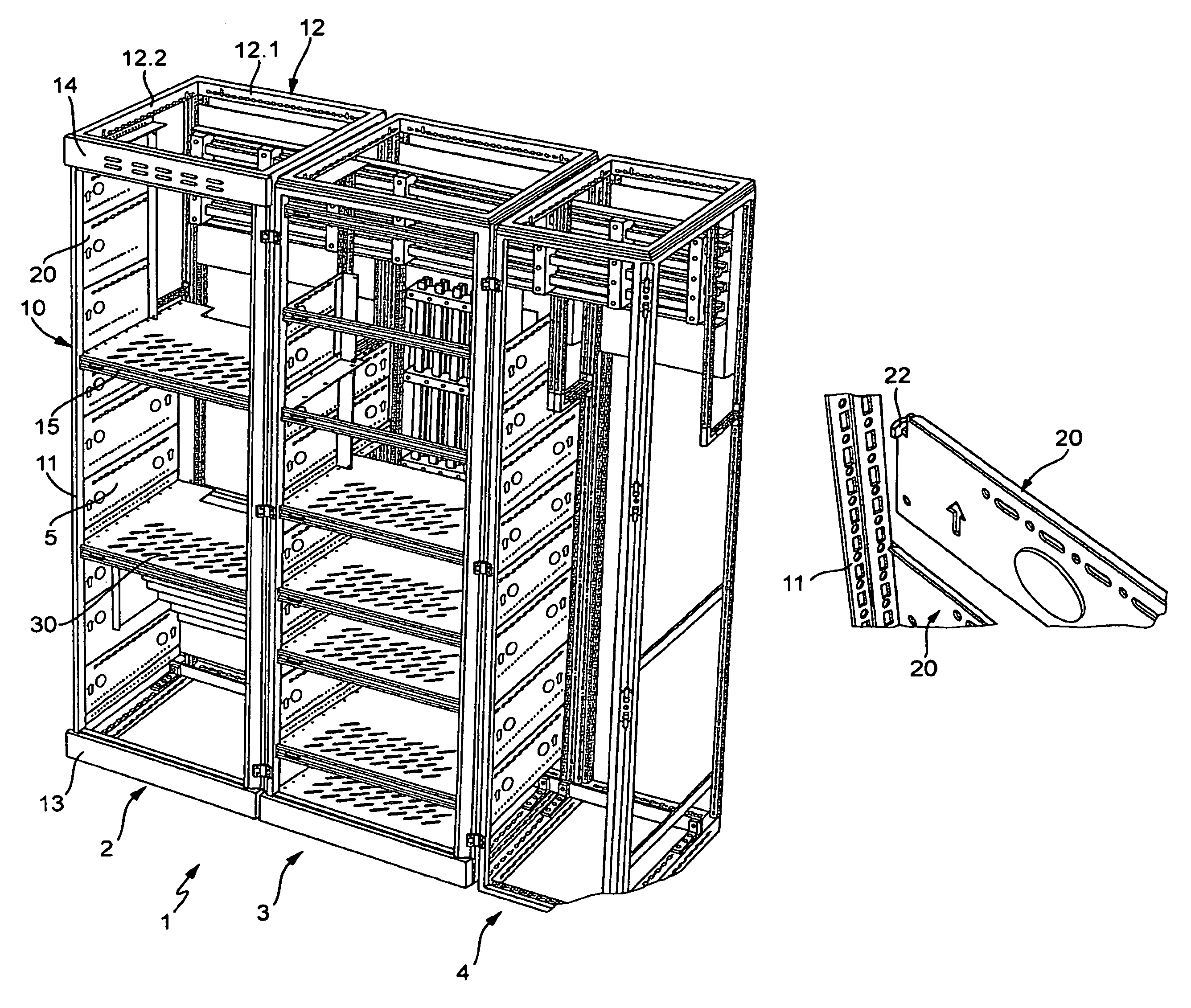
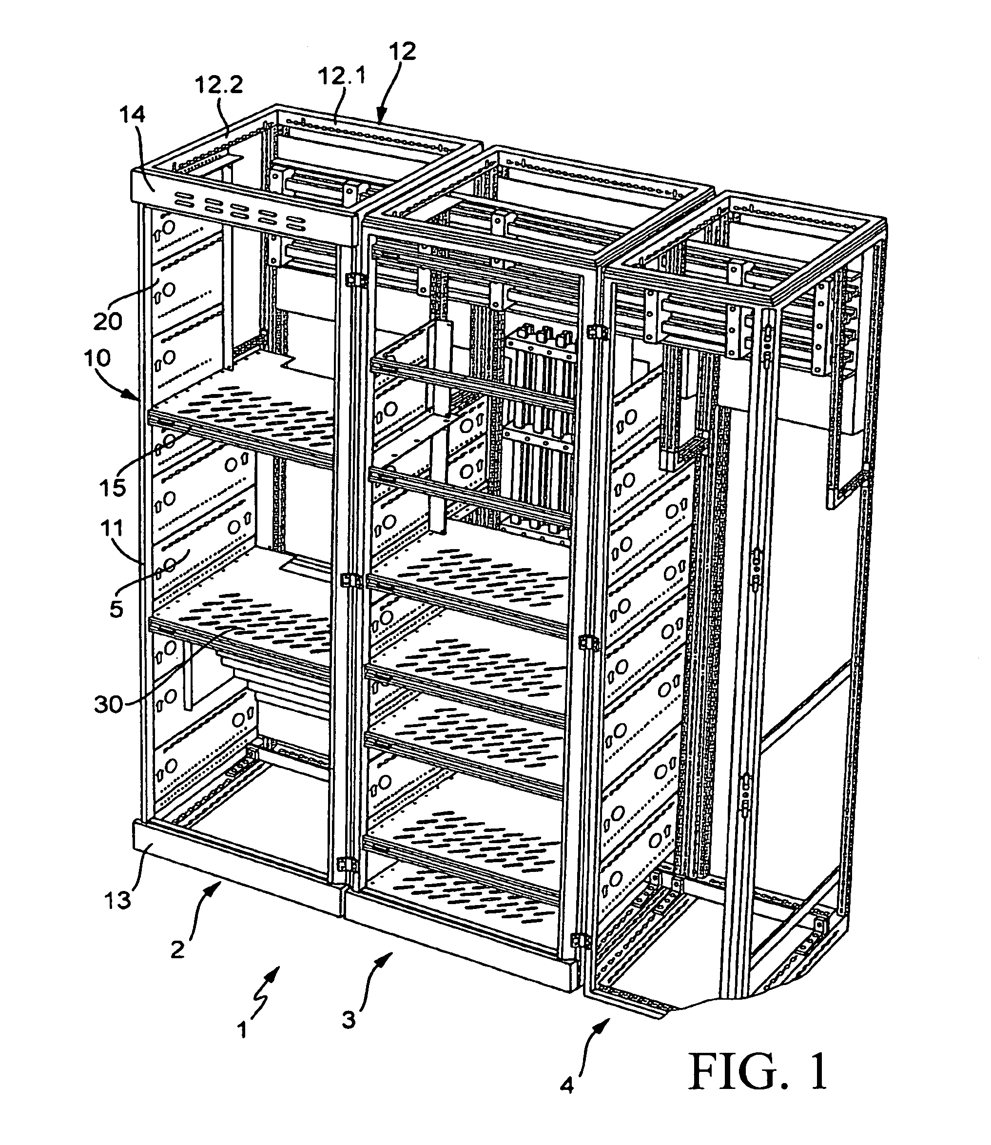
[0038]FIG. 1 shows a control box arrangement 1 with a plurality of control boxes 2, 3, 4 situated in a row, with their respective frames next to one another. The right control box has a narrower width than the other two control boxes 2, 3 and has only one continuous inner compartment, extending from the top to the bottom, whereas the two other control boxes 2, 3 have a plurality of horizontal compartments 5 situated or positioned one above the other, embodied in the form of functional compartments of different heights. In the rear region of the control box arrangement 1, there is a main rail system with a plurality of horizontally extending conductor rails, while in the middle control box 3, there are vertical distributing rails that are connected to the main rails by electrically conductive connecting elements with adapted current-carrying properties. The distributing rails extend vertically through a plurality of functional compartments and are mounted by corresponding bus bar hol...


PUM


Abstract

A control box arrangement including at least one control box which is sub-divided, or can be sub-divided, by vertical wall sections with a horizontal sub-division, into a plurality of cuboid compartments surrounded on all sides. A variable structural design of compartments, particularly functional compartments, for example for low voltage systems, is obtained by providing wall sections including lateral wall sections adapted to the same or different compartment heights, adapted rear wall sections embodied as mounting plates, and horizontal partition bottoms, in order to produce a plurality of horizontal compartments, in the form of pigeonholes, arranged one above the other.

Description

BACKGROUND OF THE INVENTION[0001]1. Field of the Invention[0002]This invention relates to a control box arrangement with at least one control box, which is or can be subdivided by wall sections into a plurality of cuboid compartments that are enclosed on all sides, for which are provided vertical wall sections with a horizontal subdivision.[0003]2. Discussion of Related Art[0004]A control box arrangement of this type, equipped with a control box, is disclosed in German Patent Reference DE 10 2004 054 173 A1. In this known control box, in order to construct a low-voltage control box that conforms to standards, the interior is divided into a plurality of compartments that are separated from one another by vertical dividing walls, namely a device compartment for devices on the side oriented toward the user, a cable connection compartment for routing cables through, and a bus bar compartment for the supply of current by bus bars electrically connected to a distributing rail system and w...

Claims


Application Information

Patent Timeline
IPC IPC(8): A47G29/00
CPCH02B1/36H02B1/301
Inventor SCHELL, MICHAELBECKER, TOBIASSTENFERT, RENE
Owner RITTALWERK RUDOLF LOH GMBH & CO KG
Why Eureka
Try Eureka